THAT Corporation; 45 Sumner Street; Milford, Massachusetts 01757; USA
Tel: (508) 478-9200; Fax: (508) 478-0990; Web: www.thatcorp.com
THAT
DBAS01E/SAP01E
De scrip tion
The THAT Digi tal BTSC Audio Sys tem
("DBAS") Encoder is a com plete, state of the art
BTSC audio proc es sor on a sin gle printed cir cuit
board. With all sig nal proc ess ing car ried out in
the digi tal do main, the DBAS01E requires no in
-
ter nal align ment, is com pletely sta ble over time
and tem pera ture, and de liv ers out stand ing ste reo
sepa ra tion and fre quency re sponse per form ance.
Equipped with its own on- board ADCs and
high- speed DAC, the THAT DBAS01E ac cepts
ana log Left, Right, and (op tion ally) SAP in put sig -
nals, and de liv ers a com plete com pos ite BTSC
ana log out put in clud ing the L+R sig nal, the AM-
DSB- SC L-R sig nal, and a pi lot sig nal locked to
an ex ter nal video sig nal at the hori zon tal scan ning
fre quency (fH).
The DBAS01E is a com pact so lu tion, as well,
meas ur ing only 4.75" x 6.75". Its op tional high-
quality SAP daugh ter board mounts on top of the
main DBAS board, re sult ing in no change to the
hori zon tal board space re quired. The en tire as
-
sem bly fits eas ily in a 1U high chas sis.
T H A T
C o r p o r a t i o n
Digital BTSC
Audio System Encoder
FEA TURES
∑
Ana log inputs and outputs
∑
DSP processing throughout
∑
Turnkey solution -- no trims or
adjustments required
∑
Completely stable performance
over time and temperature
∑
Bessel null test tone mode
AP PLI CA TIONS
∑
CATV BTSC Encoders
∑
Broad cast TV BTSC Encoders
∑
Re-transmission Equipment
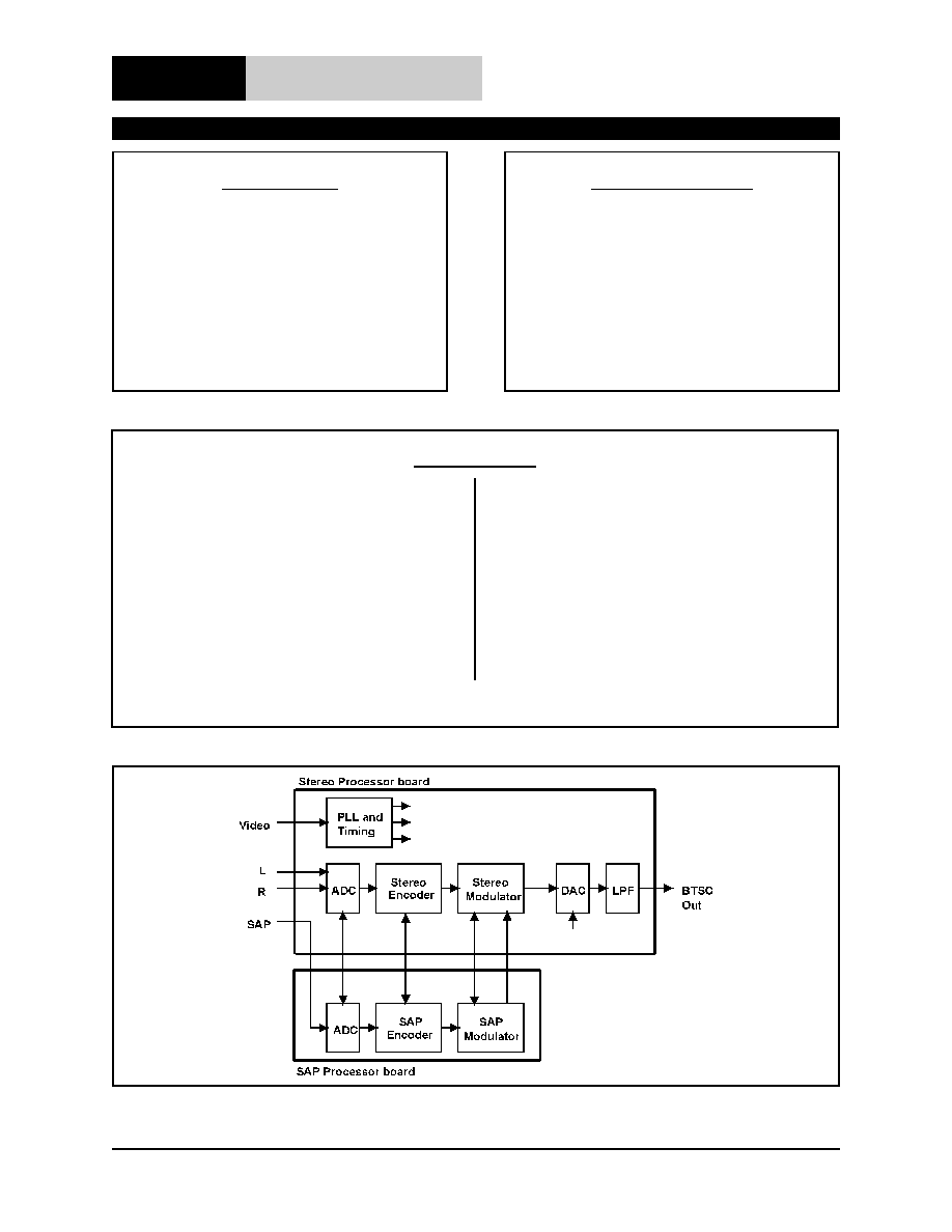
Fig ure 1. DBAS block diagram

Page 2
Digi tal BTSC Audio Sys tem Encoder
THAT Corporation; 45 Sumner Street; Milford, Massachusetts 01757; USA
Tel: (508) 478-9200; Fax: (508) 478-0990; Web: www.thatcorp.com
Ab so lute Maxi mum Rat ings (T
A
= 25∞C)
Op er at ing Tem pera ture Range (T
OP
)
0 to +70∞C
Stor age Tem pera ture Range (T
ST
)
-40 to +125∞C
Elec tri cal Char ac ter is tics
1 , 2
Stereo Processor
Pa rame ter
Sym bol
Con di tions
Min
Typ
Max
Units
Power
Power Sup ply 1
V
D
365 mA max
+4.75
+5
+5.25
VDC
Power Sup ply 2 (pos.)
V
CC
60 mA max
+11.4
+12
+12.6
VDC
Power Sup ply 2 (neg.)
V
EE
20 mA max
-12.6
-12
-11.4
VDC
Audio
In put Over load Level
V
IN
L and R inputs
2.7
3.0
Vp-p
In put Im ped ance
Z
IN
L and R in puts
10.0
k
Out put Over load Level
V
OUT
BTSC Comp. Out; 10k
load
3.0
2.0
dBV
Out put Im ped ance
Z
OUT
BTSC Comp. Out
71
75
79
Mini mum Re sis tive Load
R
L
600
Maxi mum Ca paci tive Load
C
L
100
pF
Sepa ra tion 1
3
SEP1
50 Hz to 200 Hz
35
40
dB
Sepa ra tion 2
3
SEP2
200 Hz to 2 kHz
35
40
dB
Sepa ra tion 3
3
SEP3
2 kHz to 14.5 kHz
30
35
dB
Dy namic Range
3
DR
max L=R in put sig nal at 400Hz
80
85
dB
50 Hz ~ 15 kHz un weighted
THD+N
at 66.7% EIM
4
THD1
100 Hz
0.07
0.1
%
THD2
1 kHz
0.15
0.2
%
THD3
10 kHz
0.5
1.0
%
SPECI FI CA TIONS
1
1. All specifications are subject to change without notice.
2. Unless otherwise noted, T
A
=25∞C, V
CC
= +12V, V
EE
= -12V, VD = +5V
3. Measured through encode/decode cycle.
4. EIM = Equivalent Input Modulation (as defined in FCC Bulletin OET-60).

Rev. 8/3/99
Page 3
THAT Corporation; 45 Sumner Street; Milford, Massachusetts 01757; USA
Tel: (508) 478-9200; Fax: (508) 478-0990; Web: www.thatcorp.com
1. All specifications are subject to change without notice.
2. Unless otherwise noted, T
A
=25∞C, V
CC
= +12V, V
EE
= -12V, VD = +5V
3. Measured through encode/decode cycle.
4. EIM = Equivalent Input Modulation (as defined in FCC Bulletin OET-60).
Elec tri cal Char ac ter is tics
1,2
(Cont'd)
Stereo Processor (Cont'd)
Pa rame ter
Sym bol
Con di tions
Min
Typ
Max
Units
Fre quency Re sponse
3
FR1
50 Hz to 14 kHz
-0.3
0.0
+0.3
dB
FR2
20 Hz to 15.2 kHz
-3.0
+3.0
dB
Video
In put Im ped ance
Z
INvid
1
Jumper se lecta ble
10.0
k
Z
INVID
2
75
In put Over load Level
V
INvid
1.5
Vp-p
Pi lot
Pi lot Fre quency
F
PILOT
lock range @ 15.734 kHz
-3
+3
Hz
(locked to video in put at f
h
)
Pi lot In jec tion
INJ
PI LOT
4.7
5.0
5.3
kHz
SAP Processor
Pa rame ter
Sym bol
Con di tions
Min
Typ
Max
Units
Power Supply 1
V
Dsap
260 mA max
+4.75
+5
+5.25
VDC
Power Sup ply 2 (pos.)
V
CCsap
40 mA max
+11.4
+12
+12.6
VDC
In put Over load Level
V
INsap
3.0
2.0
dBV
Fre quency Re sponse
3
FR1
sap
50 Hz to 10 kHz
-0.3
0.0
+0.3
dB
FR2
sap
20 Hz to 10.5 kHz
-3
dB
Dy namic Range
3
DR
sap
65
70
dB
THD+N
at 66.7% EIM
4
THD
sap
1
100 Hz
0.2
0.3
%
THD
sap
2
1 kHz
0.4
0.5
%
THD
sap
3
5 kHz
0.5
0.6
%
Application Information
The core of the THAT Digi tal BTSC Audio Sys -
tem Encoder is a Mo torola 56002 DSP run ning at
66 MHz. This DSP pro vides com plete BTSC base -
band sig nal proc ess ing in clud ing the ma trix
function, sum- channel and difference- channel
proc ess ing (in clud ing dbx- TV
TM
Noise Re duc tion
en cod ing), and low- pass fil ter ing. A sepa rate
20 MHz Ana log De vices 2104 DSP per forms the
AM double- side- band sup pressed car rier (DSB- SC)
modu la tion of the dbx- TV en coded dif fer ence chan -
nel and pi lot tone in jec tion.
An internal test tone mode gen er ates the pre
-
cise fre quency and am pli tude sig nal nec es sary for
per form ing a Bes sel null cali bra tion to align the
out put sig nal level to an ex ter nal FM modu la tor.
The pi lot tone and sub- carrier are phase-
locked to an ex ter nal video ref er ence by way of an
ex ter nal video sig nal in put.
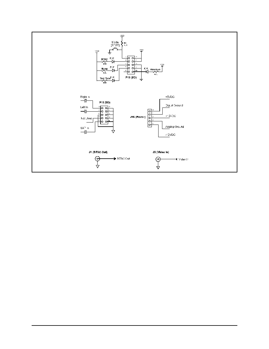
Power and sig nals in ter face to the board by way
of a number of con nec tors. In ad di tion, there are -
five gen eral pur pose I/O pins which can be cus tom -
ized to pro vide an in ter face for con trol and
in di ca tor func tions. The board ships in a de fault
con figu ra tion, and the pin outs and ex ter nal cir cuit
in for ma tion are shown in Fig ures 2 and 3. In ter -
ested cus tom ers should con tact THAT Cor po ra tion
for more in for ma tion on al ter na tive in ter faces, and
on adapt ing the DBAS01E en coder firm ware for
par ticu lar ap pli ca tions.
Note that all in put sig nals should be AC cou -
pled to the DBAS board. A 22
µ
F value for the cou -
pling ca paci tors is rec om mended.
The Video In put im ped ance is con trolled by the
jumper at P8:
Jumper open
High im ped ance
Jumper in stalled
75
im ped ance
Page 4
Digi tal BTSC Audio Sys tem Encoder
THAT Corporation; 45 Sumner Street; Milford, Massachusetts 01757; USA
Tel: (508) 478-9200; Fax: (508) 478-0990; Web: www.thatcorp.com
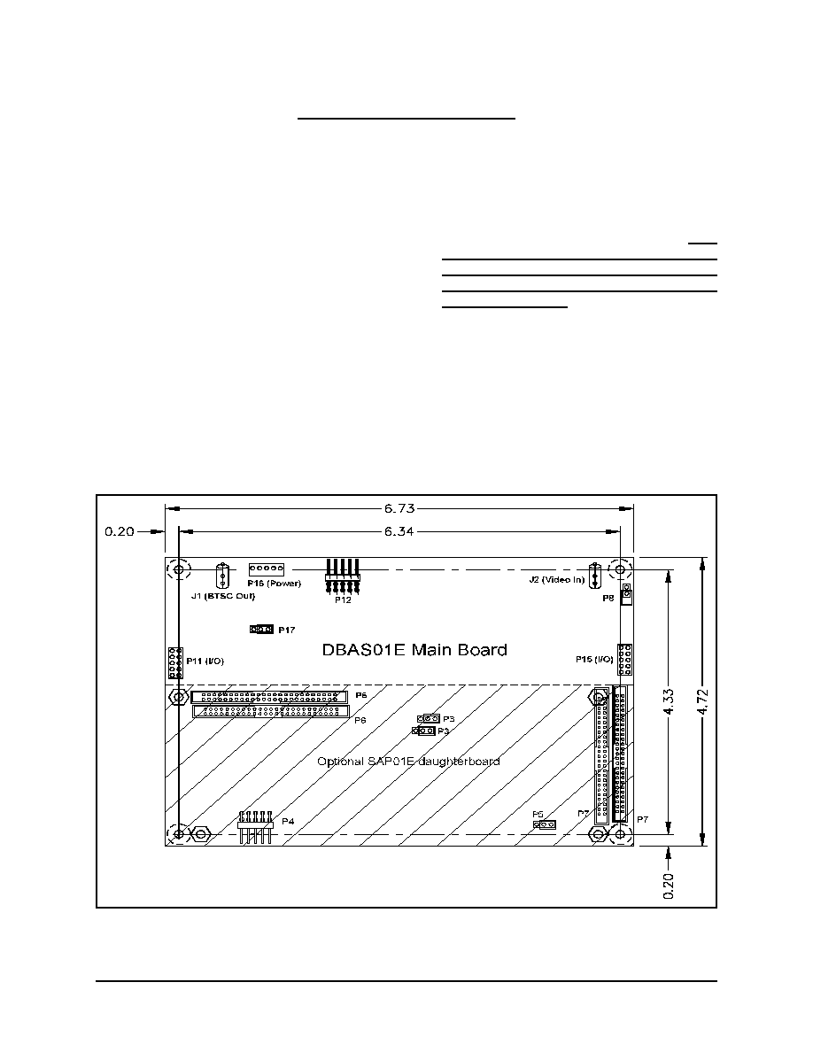
Fig ure 2. DBAS01E main board lay out
SAP01E com po nents and la bels are drawn lighter; dimen sions are in inches.
An op tional ex ter nal daugh ter card pro vides Sec -
ond Audio Pro gram (SAP) en cod ing ca pa bil ity. This
board also uses a Mo torola 56002 for audio proc ess
-
ing (again in clud ing dbx- TV Noise Re duc tion en cod -
ing), and a sepa rate Ana log De vices 2104 for the FM
modu la tion func tion.
To at tach the SAP01E daugh ter board to the
DBAS01E main board, re fer to Fig ure 4 and fol low
this pro ce dure:
∑
At tach the rib bon ca ble (sup plied with the
SAP01E) to con nec tor P6 on the DBAS01E.
Hold ing the SAP01E ver ti cally in prox im ity to
the DBAS board, at tach the other end of the rib -
bon ca ble to con nec tor P6 on the SAP board.
∑
Align the SAP01E with the spac ers on the DBAS
board, and attach us ing the sup plied screws and
wash ers.
∑
To in form the DBAS01E that a SAP board is
pres ent, install the jumper (shunt) sup plied with
the SAP01E so as to con nect pins 3 and 4 of
con nec tor P9 on the DBAS01E board as shown
in Fig ure 4.
The SAP01E in stal la tion pro ce dure is now com -
plete. No other con nec tions should be made be tween
the DBAS01E and SAP01E.
NOTE: Aside from jump ers P8 and P9 on the
DBAS01E, do NOT re move or change the jumper lo -
ca tions with out in struc tions from THAT Cor po ra tion
tech ni cal per son nel. The cor rect po si tions for all
jump ers (ex cept for the P9 shunt, in stalled only when
a SAP board is pres ent) are shown in Fig ure 2, and
the DBAS01E is shipped in this con figu ra tion.
A sepa rate dem on stra tion fix ture (DBAS DEMO-E)
is also avail able to fa cili tate power and sig nal con nec -
tions to the DBAS (and SAP) boards. Equipped with
con ven ient in put and out put con nec tors, push but ton
Rev. 8/3/99
Page 5
THAT Corporation; 45 Sumner Street; Milford, Massachusetts 01757; USA
Tel: (508) 478-9200; Fax: (508) 478-0990; Web: www.thatcorp.com
Fig ure 3. DBAS01E pin out and hookup in for mation