Document Outline
- FEATURES
- APPLICATIONS
- DESCRIPTION
- SPECIFICATIONS
- PIN CONFIGURATION
- PIN DESCRIPTIONS
- ABSOLUTE MAXIMUM RATINGS
- PACKAGE/ORDERING INFORMATION
- BASIC OPERATION
- TYPICAL PERFORMANCE CURVES
- INTRODUCTION
- SAMPLE-AND-HOLD SECTION
- REFERENCE
- ANALOG INPUT
- TRANSITION NOISE
- BIPOLAR INPUTS
- TIMING AND CONTROL
- TIMING SPECIFICATIONS
- SECTION A
- SECTION B
- SECTION C
- READING DATA
- LAYOUT
- APPLICATIONS
- PACKAGE DRAWING

Dual 500kHz, 12-Bit, 2 + 2 Channel
Simultaneous Sampling
ANALOG-TO-DIGITAL CONVERTER
FEATURES
q
4 INPUT CHANNELS
q
FULLY DIFFERENTIAL INPUTS
q
2
µ
s TOTAL THROUGHPUT PER CHANNEL
q
GUARANTEED NO MISSING CODES
q
PARALLEL INTERFACE
q
1MHz EFFECTIVE SAMPLING RATE
q
LOW POWER: 40mW
APPLICATIONS
q
MOTOR CONTROL
q
MULTI-AXIS POSITIONING SYSTEMS
q
3-PHASE POWER CONTROL
DESCRIPTION
The ADS7862 is a dual 12-bit, 500kHz analog-to-digital
converter (A/D) with 4 fully differential input channels grouped
into two pairs for high speed simultaneous signal acquisition.
Inputs to the sample-and-hold amplifiers are fully differential
and are maintained differential to the input of the A/D con-
verter. This provides excellent common-mode rejection of
80dB at 50kHz, which is important in high noise environ-
ments.
The ADS7862 offers parallel interface and control inputs to
minimize software overhead. The output data for each channel
is available as a 12-bit word. The ADS7862 is offered in an
TQFP-32 package and is fully specified over the ≠40
∞
C to
+85
∞
C operating range.
ADS7862
SAR
Interface
Conversion
and
Control
Output
Registers
COMP
CONVST
BUSY
RD
CS
Data Output
12
CLOCK
A0
CDAC
Internal
2.5V
Reference
S/H
Amp
S/H
Amp
CH A0≠
CH A0+
REF
IN
CH A1≠
CH A1+
SAR
COMP
CDAC
MUX
MUX
CH B0≠
CH B0+
CH B1≠
CH B1+
REF
OUT
ADS7862
§
SBAS101A ≠ JANUARY 1998 ≠ REVISED JUNE 2003
www.ti.com
PRODUCTION DATA information is current as of publication date.
Products conform to specifications per the terms of Texas Instruments
standard warranty. Production processing does not necessarily include
testing of all parameters.
Copyright © 1998-2003, Texas Instruments Incorporated
Please be aware that an important notice concerning availability, standard warranty, and use in critical applications of
Texas Instruments semiconductor products and disclaimers thereto appears at the end of this data sheet.

2
ADS7862
Æ
SPECIFICATIONS
All specifications T
MIN
to T
MAX
, +V
A
= +V
D
= +5V, V
REF
= internal +2.5V and f
CLK
= 8MHz, f
SAMPLE
= 500kHz, unless otherwise noted.
The information provided herein is believed to be reliable; however, BURR-BROWN assumes no responsibility for inaccuracies or omissions. BURR-BROWN assumes
no responsibility for the use of this information, and all use of such information shall be entirely at the user's own risk. Prices and specifications are subject to change
without notice. No patent rights or licenses to any of the circuits described herein are implied or granted to any third party. BURR-BROWN does not authorize or warrant
any BURR-BROWN product for use in life support devices and/or systems.
ADS7862Y
ADS7862YB
PARAMETER
CONDITIONS
MIN
TYP
MAX
MIN
TYP
MAX
UNITS
RESOLUTION
12
Bits
ANALOG INPUT
Input Voltage Range-Bipolar
V
CENTER
= Internal V
REF
at 2.5V
≠V
REF
+V
REF
V
Absolute Input Range
+IN
≠0.3
V
CC
+ 0.3
V
≠IN
≠0.3
V
CC
+ 0.3
V
Input Capacitance
15
pF
Input Leakage Current
CLK = GND
±
1
µ
A
SYSTEM PERFORMANCE
No Missing Codes
12
Bits
Integral Linearity
±
0.75
±
2
±
0.5
±
1
LSB
Integral Linearity Match
0.5
1
LSB
Differential Linearity
±
0.75
±
0.5
±
1
LSB
Bipolar Offset Error
Referenced to REF
IN
±
0.75
±
3
±
0.5
±
2
LSB
Bipolar Offset Error Match
3
2
LSB
Positive Gain Error
Referenced to REF
IN
±
0.15
±
0.75
±
0.1
±
0.5
% of FSR
Positive Gain Error Match
2
1
LSB
Negative Gain Error
Referenced to REF
IN
±
0.15
±
0.75
±
0.1
±
0.5
% of FSR
Negative Gain Error Match
2
1
LSB
Common-Mode Rejection Ratio
At DC
80
dB
V
IN
=
±
1.25Vp-p at 50kHz
80
dB
Noise
120
µ
Vrms
Power Supply Rejection Ratio
±
0.5
±
2
LSB
SAMPLING DYNAMICS
Conversion Time per A/D
1.75
µ
s
Acquisition Time
0.25
µ
s
Throughput Rate
500
kHz
Aperture Delay
3.5
ns
Aperture Delay Matching
100
ps
Aperture Jitter
50
ps
Small-Signal Bandwidth
40
MHz
DYNAMIC CHARACTERISTICS
Total Harmonic Distortion
V
IN
=
±
2.5Vp-p at 100kHz
75
dB
SINAD
V
IN
=
±
2.5Vp-p at 100kHz
71
dB
Spurious Free Dynamic Range
V
IN
=
±
2.5Vp-p at 100kHz
≠78
dB
Channel-to-Channel Isolation
V
IN
=
±
2.5Vp-p at 100kHz
≠80
dB
VOLTAGE REFERENCE
Internal
2.475
2.5
2.525
V
Internal Drift
±
25
ppm/
∞
C
Internal Noise
50
µ
Vp-p
Internal Source Current
2
mA
Internal Load Rejection
0.005
mV/
µ
A
Internal PSRR
65
dB
External Voltage Range
1.2
2.5
2.6
V
Input Current
0.05
1
µ
A
Input Capacitance
5
pF
DIGITAL INPUT/OUTPUT
Logic Family
CMOS
Logic Levels: V
IH
I
IH
= +5
µ
A
3.0
+V
DD
+ 0.3
V
V
IL
I
IL
= +5
µ
A
≠0.3
0.8
V
V
OH
I
OH
= ≠500
µ
A
3.5
V
V
OL
I
OL
= 500
µ
A
0.4
V
External Clock
0.2
8
MHz
Data Format
Binary Two's Complement
POWER SUPPLY REQUIREMENTS
Power Supply Voltage, +V
4.75
5
5.25
V
Quiescent Current, +V
A
5
8
mA
Power Dissipation
25
40
mW
Specifications same as ADS7862Y.

3
ADS7862
Æ
PIN
NAME
DESCRIPTION
1
REF
IN
Reference Input
2
REF
OUT
+2.5V Reference Output. Connect directly to REF
IN
(pin 1) when using internal reference.
3
AGND
Analog Ground
4
+V
A
Analog Power Supply, +5VDC. Connect directly to
digital power supply (pin 24). Decouple to analog
ground with a 0.1
µ
F ceramic capacitor and a 10
µ
F
tantalum capacitor.
5
DB11
Data Bit 11, MSB
6
DB10
Data Bit 10
7
DB9
Data Bit 9
8
DB8
Data Bit 8
9
DB7
Data Bit 7
10
DB6
Data Bit 6
11
DB5
Data Bit 5
12
DB4
Data Bit 4
13
DB3
Data Bit 3
14
DB2
Data Bit 2
15
DB1
Data Bit 1
16
DB0
Data Bit 0, LSB
17
BUSY
HIGH when a conversion is in progress.
18
CONVST
Convert Start
19
CLOCK
An external CMOS-compatible clock can be applied to
the CLOCK input to synchronize the conversion pro-
cess to an external source. The CLOCK pin controls
the sampling rate by the equation: CLOCK 16 ∑ f
SAMPLE
.
20
CS
Chip Select
21
RD
Synchronization pulse for the parallel output. During a
Read operation, the first falling edge selects the A
register and the second edge selects the B register,
A0, then controls whether input 0 or input 1 is read.
22
A0
On the falling edge of Convert Start, when A0 is LOW
Channel A0 and Channel B0 are converted and when
it is HIGH, Channel A1 and Channel B1 are converted.
During a Read operation, the first falling edge selects
the A register and the second edge selects the B of RD
register, A0, then controls whether input 0 or input 1 is
read.
23
DGND
Digital Ground. Connect directly to analog ground (pin 3).
24
+V
D
Digital Power Supply, +5VDC
25
CH B1+
Non-Inverting Input Channel B1
26
CH B1≠
Inverting Input Channel B1
27
CH B0+
Non-Inverting Input Channel B0
28
CH B0≠
Inverting Input Channel B0
29
CH A1≠
Inverting Input Channel A1
30
CH A1+
Non-Inverting Input Channel A1
31
CH A0≠
Inverting Input Channel A0
32
CH A0+
Non-Inverting Input Channel A0
PIN CONFIGURATION
Top View
PIN DESCRIPTIONS
ABSOLUTE MAXIMUM RATINGS
Analog Inputs to AGND: Any Channel Input ........ ≠0.3V to (+V
D
+ 0.3V)
REF
IN
............................. ≠0.3V to (+V
D
+ 0.3V)
Digital Inputs to DGND .......................................... ≠0.3V to (+V
D
+ 0.3V)
Ground Voltage Differences: AGND, DGND ...................................
±
0.3V
+V
D
to AGND ......................... ≠0.3V to +6V
Power Dissipation .......................................................................... 325mW
Maximum Junction Temperature ................................................... +150
∞
C
Operating Temperature Range ........................................ ≠40
∞
C to +85
∞
C
Storage Temperature Range ......................................... ≠65
∞
C to +150
∞
C
Lead Temperature (soldering, 10s) ............................................... +300
∞
C
ELECTROSTATIC
DISCHARGE SENSITIVITY
This integrated circuit can be damaged by ESD. Burr-Brown
recommends that all integrated circuits be handled with
appropriate precautions. Failure to observe proper handling and
installation procedures can cause damage.
ESD damage can range from subtle performance degradation to
complete device failure. Precision integrated circuits may be
more susceptible to damage because very small parametric
changes could cause the device not to meet its published specifi-
cations.
REF
IN
REF
OUT
AGND
+V
A
DB11
DB10
DB9
DB8
1
2
3
4
5
6
7
8
24
23
22
21
20
19
18
17
+V
D
DGND
A0
RD
CS
CLOCK
CONVST
BUSY
DB7
DB6
DB5
DB4
DB3
DB2
DB1
DB0
9
10
11
12
13
14
15
16
CH A0+
CH A0
≠
CH A1+
CH A1
≠
CH B0
≠
CH B0+
CH B1
≠
CH B1+
32
31
30
29
28
ADS7862
27
26
25
4
ADS7862
Æ
PACKAGE/ORDERING INFORMATION
MAXIMUM
MAXIMUM
RELATIVE
GAIN
PACKAGE
SPECIFICATION
ACCURACY
ERROR
DRAWING
TEMPERATURE
ORDERING
TRANSPORT
PRODUCT
(LSB)
(%)
PACKAGE
NUMBER
(1)
RANGE
NUMBER
(2)
MEDIA
ADS7862Y
±
2
±
0.75
TQFP-32
351
≠40
∞
C to +85
∞
C
ADS7862Y/250
Tape and Reel
ADS7862Y
"
"
"
"
"
ADS7862Y/2K5
Tape and Reel
ADS7862YB
±
1
±
0.5
TQFP-32
351
≠40
∞
C to +85
∞
C
ADS7862YB/250
Tape and Reel
ADS7862YB
"
"
"
"
"
ADS7862YB/2K5
Tape and Reel
NOTE: (1) For detail drawing and dimension table, please see end of data sheet or Package Drawing File on Web. (2) Models with a slash(/) are available only
in Tape and reel in quantities indicated (e.g. /250 indicates 250 units per reel, /2K5 indicates 2500 devices per reel). Ordering 2500 pieces of "ADS7862Y/2K5"
will get a single 2500-piece Tape and Reel. For detailed Tape and Reel mechanical information, refer to the www.burr-brown.com web site under Applications and
Tape and Reel Orientation and Dimensions.
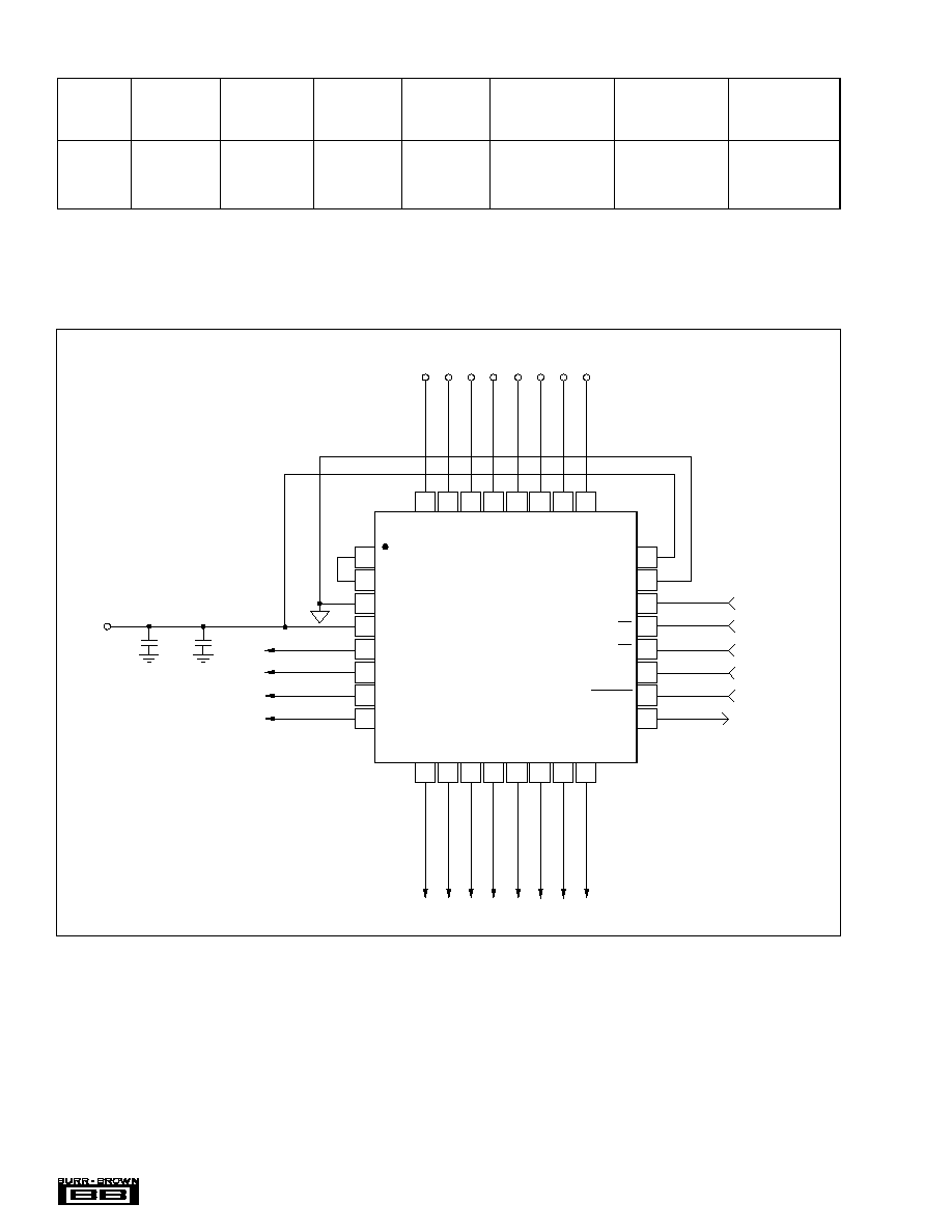
BASIC OPERATION
REF
IN
REF
OUT
AGND
+V
A
DB11
DB10
DB9
DB8
1
2
3
4
5
6
7
8
24
23
22
21
20
19
18
17
+V
D
DGND
A0
RD
CS
CLOCK
CONVST
BUSY
Address Select
Read Input
Chip Select
Clock Input
Conversion Start
Busy Output
ADS7862Y
10
µ
F
+
0.1
µ
F
+5V
Analog Supply
+
32
31
30
29
28
27
26
25
CH A0+
CH A0
≠
CH A1+
CH A1
≠
CH B0
≠
CH B0+
CH B1
≠
CH B1+
9
10
11
12
13
14
15
16
DB7
DB6
DB5
DB4
DB3
DB2
DB1
DB0
5
ADS7862
Æ
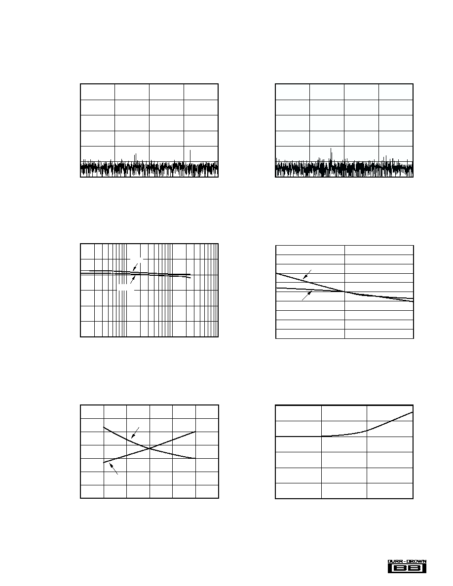
FREQUENCY SPECTRUM
(4096 Point FFT; f
IN
= 199.9kHz, ≠0.5dB)
Frequency (kHz)
0
≠20
≠40
≠60
≠80
≠100
≠120
Amplitude (dB)
0
62.5
125
250
187.5
TYPICAL PERFORMANCE CURVES
At T
A
= +25
∞
C, +V
A
= +V
D
= +5V, V
REF
= internal +2.5V and f
CLK
= 8MHz, f
SAMPLE
= 500kHz, unless otherwise noted.
FREQUENCY SPECTRUM
(4096 Point FFT; f
IN
= 99.9kHz, ≠0.5dB)
Frequency (kHz)
0
≠20
≠40
≠60
≠80
≠100
≠120
Amplitude (dB)
0
62.5
125
250
187.5
CHANGE IN SIGNAL-TO-NOISE RATIO
AND SIGNAL-TO-(NOISE+DISTORTION)
vs TEMPERATURE
Temperature (
∞
C)
0.25
0.2
0.15
0.1
0.05
0
≠0.05
≠0.1
≠0.15
≠0.2
≠0.25
Delta from +25
∞
C (dB)
≠40
25
85
SNR
SINAD
CHANGE IN SPURIOUS FREE DYNAMIC RANGE
AND TOTAL HARMONIC DISTORTION
vs TEMPERATURE
Temperature (
∞
C)
0.65
0.45
0.25
0.05
≠0.15
≠0.35
≠0.55
≠0.75
0.65
0.45
0.25
0.05
≠0.15
≠0.35
≠0.55
≠0.75
SFDR Delta from +25
∞
C (dB)
THD Delta from +25
∞
C (dB)
≠40
25
85
SFDR
THD
CHANGE IN POSITIVE GAIN MATCH
vs TEMPERATURE
(Maximum Deviation for All Four Channels)
Temperature (
∞
C)
0.6
0.5
0.4
0.3
0.2
0.1
0
Change in Positive Gain Match (LSB)
≠40
25
85
150
SIGNAL-TO-NOISE RATIO AND
SIGNAL-TO-(NOISE+DISTORTION)
vs INPUT FREQUENCY
10k
100k
1k
1M
Input Frequency (Hz)
SNR and SINAD (dB)
74
72
70
68
66
64
76
SINAD
SNR