
FEATURES
D
LOW OFFSET VOLTAGE: 5
µ
V (max)
D
ZERO DRIFT: 0.05
µ
V/
∞
C max
D
QUIESCENT CURRENT: 750
µ
A (max)
D
SINGLE-SUPPLY OPERATION
D
LOW BIAS CURRENT: 200pA (max)
D
SHUTDOWN
D
MicroSIZE PACKAGES
D
WIDE SUPPLY RANGE: 2.7V to 12V
APPLICATIONS
D
TRANSDUCER APPLICATIONS
D
TEMPERATURE MEASUREMENTS
D
ELECTRONIC SCALES
D
MEDICAL INSTRUMENTATION
D
BATTERY-POWERED INSTRUMENTS
D
HANDHELD TEST EQUIPMENT
DESCRIPTION
The OPA734 and OPA735 series of CMOS operational
amplifiers use auto-zeroing techniques to simultaneously
provide low offset voltage (5
µ
V max) and near-zero drift
over time and temperature. These miniature, high-preci-
sion, low quiescent current amplifiers offer high input
impedance and rail-to-rail output swing within 50mV of the
rails. Either single or bipolar supplies can be used in the
range of +2.7V to +12V (
±
1.35V to
±
6V). They are
optimized for low-voltage, single-supply operation.
The OPA734 family includes a shutdown mode. Under
logic control, the amplifiers can be switched from normal
operation to a standby current that is 9
µ
A (max) and the
output placed in a high-impedance state.
The single version is available in the MicroSIZE SOT23-5
(SOT23-6 for shutdown version) and the SO-8 packages.
The dual version is available in the MSOP-8 and SO-8
packages (MSOP-10 only for the shutdown version). All
versions are specified for operation from -40
∞
C to +85
∞
C.
1/2
OP A 2735
R
3
10k
R
3
10k
R
1
1k
1/2
OP A 2735
R
2
1k
C
4
1nF
C
4
1nF
R
G
10V
C
1
1nF
C
2
10nF
C
3
1nF
V
REF
= 15V
REF102
G = 1 + 2
R
3
R
G
OPA734, OPA2734
OPA735, OPA2735
SBOS282A - DECEMBER 2003 - REVISED FEBRUARY 2004
0.05
µ
V/
∞
C max, SINGLE-SUPPLY CMOS
OPERATIONAL AMPLIFIERS
Zer
-Drift Series
PRODUCTION DATA information is current as of publication date. Products
conform to specifications per the terms of Texas Instruments standard warranty.
Production processing does not necessarily include testing of all parameters.
www.ti.com
Copyright
2003-2004, Texas Instruments Incorporated
Please be aware that an important notice concerning availability, standard warranty, and use in critical applications of Texas Instruments
semiconductor products and disclaimers thereto appears at the end of this data sheet.
All trademarks are the property of their respective owners.

OPA734, OPA2734
OPA735, OPA2735
SBOS282A - DECEMBER 2003 - REVISED FEBRUARY 2004
www.ti.com
2
ABSOLUTE MAXIMUM RATINGS
(1)
Supply Voltage
+13.2V
. . . . . . . . . . . . . . . . . . . . . . . . . . . . . . . . . . . . . . . . . . .
Signal Input Terminals, Voltage(2)
(V-) - 0.5V to (V+) + 0.5V
. . . . . . . . . . .
Current(2)
±
10mA
. . . . . . . . . . . . . . . . . . . . . . . . . . .
Output Short Circuit(3) Continuous
. . . . . . . . . . . . . . . . . . . . . . . . . . . . . . . . .
Operating Temperature
-40
∞
C to +150
∞
C
. . . . . . . . . . . . . . . . . . . . . . . . . . . .
Storage Temperature
-65
∞
C to +150
∞
C
. . . . . . . . . . . . . . . . . . . . . . . . . . . . . .
Junction Temperature
+150
∞
C
. . . . . . . . . . . . . . . . . . . . . . . . . . . . . . . . . . . . .
Lead Temperature (soldering, 10s)
+300
∞
C
. . . . . . . . . . . . . . . . . . . . . . . . . . .
ESD Rating (Human Body Model), OPA734
1000V
. . . . . . . . . . . . . . . . . . . .
ESD Rating (Human Body Model), OPA735, OPA2734, OPA2735
2000V
. . . .
(1) Stresses above these ratings may cause permanent damage. Exposure
to absolute maximum conditions for extended periods may degrade
device reliability. These are stress ratings only, and functional operation of
the device at these or any other conditions beyond those specified is not
implied.
(2) Input terminals are diode-clamped to the power-supply rails. Input signals
that can swing more than 0.5V beyond the supply rails should be current
limited to 10mA or less.
(3) Short-circuit to ground, one amplifier per package.
This integrated circuit can be damaged by ESD. Texas
Instruments recommends that all integrated circuits be
handled with appropriate precautions. Failure to observe
proper handling and installation procedures can cause damage.
ESD damage can range from subtle performance degradation to
complete device failure. Precision integrated circuits may be more
susceptible to damage because very small parametric changes could
cause the device not to meet its published specifications.
PACKAGE/ORDERING INFORMATION
PRODUCT
PACKAGE-LEAD
PACKAGE
DESIGNATOR(1)
SPECIFIED
TEMPERATURE
RANGE
PACKAGE
MARKING
ORDERING
NUMBER
TRANSPORT MEDIA,
QUANTITY
Shutdown Version
OPA734
SOT23-6
DBV
-40
∞
C to +85
∞
C
NSB
OPA734AIDBVT
Tape and Reel, 250
OPA734AIDBVR
Tape and Reel, 3000
OPA734
SO-8
D
-40
∞
C to +85
∞
C
OPA734A
OPA734AID
Rails, 100
OPA734AIDR
Tape and Reel, 2500
OPA2734
MSOP-10
DGS
-40
∞
C to +85
∞
C
BGO
OPA2734AIDGST
Tape and Reel, 250
OPA2734AIDGSR
Tape and Reel, 2500
Non-Shutdown Version
OPA735
SOT23-5
DBV
-40
∞
C to +85
∞
C
NSC
OPA735AIDBVT
Tape and Reel, 250
OPA735AIDBVR
Tape and Reel, 3000
OPA735
SO-8
D
-40
∞
C to +85
∞
C
OPA735A
OPA735AID
Rails, 100
OPA735AIDR
Tape and Reel, 2500
OPA2735
SO-8
D
-40
∞
C to +85
∞
C
OPA2735A
OPA2735AID
Rails, 100
OPA2735AIDR
Tape and Reel, 2500
OPA2735
MSOP-8
DGK
-40
∞
C to +85
∞
C
BGN
OPA2735AIDGKT
Tape and Reel, 250
OPA2735AIDGKR
Tape and Reel, 2500
(1) For the most current specification and package information, refer to our web site at www.ti.com.

OPA734, OPA2734
OPA735, OPA2735
SBOS282A - DECEMBER 2003 - REVISED FEBRUARY 2004
www.ti.com
3
ELECTRICAL CHARACTERISTICS: V
S
=
±
5V (V
S
= +10V)
Boldface limits apply over the specified temperature range, T
A
= -40
∞
C to +85
∞
C.
At TA = +25
∞
C, RL = 10k
connected to VS/2, and VOUT = VS/2, unless otherwise noted.
OPA734, OPA2734, OPA735, OPA2735
PARAMETER
CONDITIONS
MIN
TYP
MAX
UNIT
OFFSET VOLTAGE
Input Offset Voltage
VOS
1
5
µ
V
vs Temperature
dVOS/dT
0.01
0.05
µ
V/
∞
C
vs Power Supply
PSRR
VS = 2.7V to 12V, VCM = 0V
0.2
1.8
µ
V/V
Long-Term Stability
Note (1)
Channel Separation, dc
0.1
µ
V/V
INPUT BIAS CURRENT
Input Bias Current
IB
VCM = VS/2
±
100
±
200
pA
over Temperature
See Typical Characteristics
pA
Input Offset Current
IOS
VCM = VS/2
±
200
±
300
pA
NOISE
Input Voltage Noise, f = 0.01Hz to 1Hz
en
1
µ
VPP
Input Voltage Noise, f = 0.1Hz to 10Hz
en
3
µ
VPP
Input Voltage Noise Density, f = 1kHz
en
150
nV/
Hz
Input Current Noise Density, f = 1kHz
in
40
fA/
Hz
INPUT VOLTAGE RANGE
Common-Mode Voltage Range
VCM
(V-) - 0.1
(V+) - 1.5
V
Common-Mode Rejection Ratio
CMRR
(V-) - 0.1V < VCM < (V+) - 1.5V
115
130
dB
INPUT CAPACITANCE
Differential
2
pF
Common-Mode
10
pF
OPEN-LOOP GAIN
Open-Loop Voltage Gain
AOL
(V-) + 100mV < VO < (V+) - 100mV
115
130
dB
FREQUENCY RESPONSE
Gain-Bandwidth Product
GBW
1.6
MHz
Slew Rate
SR
G = +1
1.5
V/
µ
s
OUTPUT
Voltage Output Swing from Rail
RL = 10k
20
50
mV
Short-Circuit Current
ISC
±
20
mA
Open-Loop Output Impedance
f = 1MHz, IO = 0
125
Capacitive Load Drive
CLOAD
See Typical Characteristics
ENABLE/SHUTDOWN
tOFF
1.5
µ
s
tON(2)
150
µ
s
VL (amplifier is shutdown)
V-
(V-) + 0.8
V
VH (amplifier is active)
(V-) + 2
V+
V
IQSD (per amplifier)
4
9
µ
A
Input Bias Current of Enable Pin
3
µ
A
POWER SUPPLY
Operating Voltage Range
VS
2.7 to 12
(
±
1.35 to
±
6)
V
Quiescent Current (per amplifier)
IQ
IO = 0
0.6
0.75
mA
TEMPERATURE RANGE
Specified Range
-40
+85
∞
C
Operating Range
-40
+150
∞
C
Storage Range
-65
+150
∞
C
Thermal Resistance
q
JA
∞
C/W
SOT23-5, SOT23-6
200
∞
C/W
MSOP-8, MSOP-10, SO-8
150
∞
C/W
(1) 300-hour life test at 150
∞
C demonstrated randomly distributed variation in the range of measurement limits--approximately 1
µ
V.
(2) Device requires one complete auto-zero cycle to return to VOS accuracy.

OPA734, OPA2734
OPA735, OPA2735
SBOS282A - DECEMBER 2003 - REVISED FEBRUARY 2004
www.ti.com
4
PIN CONFIGURATIONS
1
2
3
5
4
V+
-
IN
Out
V
-
+IN
OPA735
SOT23-5
1
2
3
4
8
7
6
5
Enable
V+
OUT
NC
(1)
NC
(1)
-
IN
+IN
V
-
OPA734
SO-8
1
2
3
4
5
10
9
8
7
6
V+
OUT B
-
IN B
+IN B
Enable B
OUT A
-
IN A
+IN A
V
-
Enable A
OPA2734
MSOP-10
(1) NC = No Connection
(2) Pin 1 of the SOT23-6 is determined by orienting the package marking as shown in the diagram.
1
2
3
4
8
7
6
5
V+
OUT B
-
IN B
+IN B
OUT A
-
IN A
+IN A
V
-
OPA2735
SO-8, MSOP-8
1
2
3
6
5
4
V+
Enable
-
IN
Out
V
-
+IN
OPA734
SOT23-6
(2)
NS
B
1
2
3
4
8
7
6
5
NC
(1)
V+
OUT
NC
(1)
NC
(1)
-
IN
+IN
V
-
OPA735
SO-8

OPA734, OPA2734
OPA735, OPA2735
SBOS282A - DECEMBER 2003 - REVISED FEBRUARY 2004
www.ti.com
5
TYPICAL CHARACTERISTICS
At TA = +25
∞
C, VS =
±
5V (same as +10V).
OUTPUT VOLTAGE PRODUCTION DISTRIBUTION
Offset Voltage (
µ
V)
P
o
pu
l
a
t
i
on
-
5.0
-
4.5
-
4.0
-
3.5
-
3.0
-
2.5
-
2.0
-
1.5
-
1.0
-
0.5
0
0.
5
1.
0
1.
5
2.
0
2.
5
3.
0
3.
5
4.
0
4.
5
5.
0
OUTPUT VOLTAGE DRIFT PRODUCTION DISTRIBUTION
Offset Voltage Drift (
µ
V/
_
C)
P
o
pu
l
a
t
i
on
0
0.00
5
0.01
0
0.01
5
0.02
0
0.02
5
0.03
0
0.03
5
0.04
0
0.04
5
0.05
0
Absolute Value;
Centered Around Zero
6
4
2
0
-
2
-
4
-
6
OUTPUT VOLTAGE SWING TO RAIL
vs OUTPUT CURRENT
Output Current (mA)
V
OU
T
Vo
l
t
a
g
e
S
w
i
n
g
(
V
)
0
5
10
15
20
25
30
35
-
40
_
C
+85
_
C
+25
_
C
1000
0
-
1000
-
2000
-
3000
-
4000
-
5000
-
6000
-
7000
-
8000
-
9000
-
10000
INPUT BIAS CURRENT vs TEMPERATURE
Temperature (
_
C)
I
n
p
u
t
B
i
as
C
u
r
r
en
t
(
p
A
)
-
50
-
25
0
25
50
75
100
125
-
I
B
+
I
B
85
V
CM
= V
-
10 Representative Units
1000
800
600
400
200
0
-
200
-
400
-
600
-
800
-
1000
INPUT BIAS CURRENT vs TEMPERATURE
Temperature (
_
C)
I
n
p
u
t
B
i
as
C
u
r
r
en
t
(
p
A
)
-
50
-
25
0
25
50
75
100
125
-
I
B
+
I
B
85
V
CM
= V
S
/2
10 Representative Units
800
600
400
200
0
SUPPLY CURRENT vs TEMPERATURE
Temperature (
_
C)
S
u
p
p
l
y
C
ur
r
e
nt
(
µ
A)
-
50
-
25
0
25
50
75
100
125
±
1.35V
±
6V

OPA734, OPA2734
OPA735, OPA2735
SBOS282A - DECEMBER 2003 - REVISED FEBRUARY 2004
www.ti.com
6
TYPICAL CHARACTERISTICS (continued)
At TA = +25
∞
C, VS =
±
5V (same as +10V).
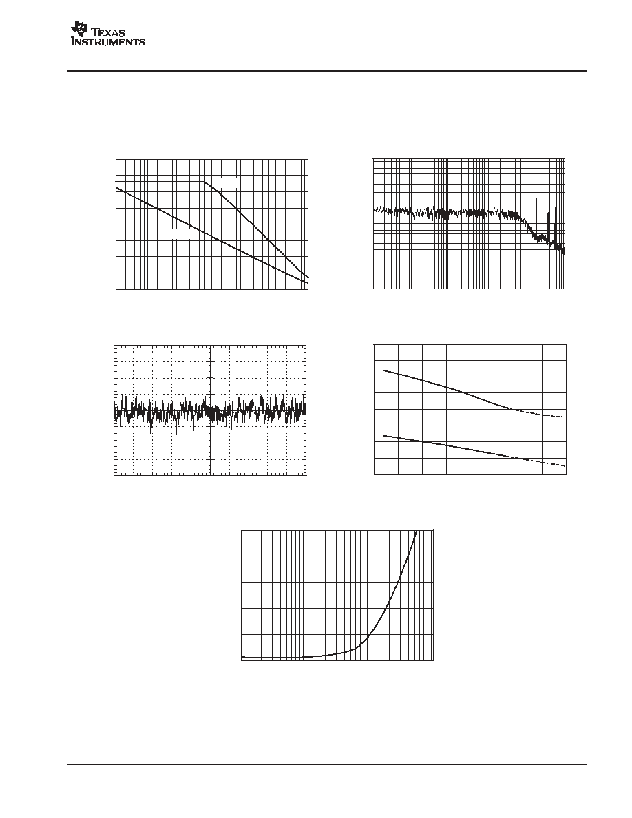
OPEN-LOOP GAIN AND PHASE MARGIN
vs FREQUENCY
A
OL
(d
B
)
P
h
as
e
M
a
r
gi
n
(
_
)
Frequency (Hz)
180
160
140
120
100
80
60
40
20
0
-
20
-
40
180
160
140
120
100
80
60
40
20
0
-
20
-
40
0.1
100
1k
10k
100k
1M
1
10
10M
LARGE-SIGNAL RESPONSE
Time (5
µ
s/div)
O
u
tput
V
o
l
t
age
(
2
V
/
di
v
)
SMALL-SIGNAL RESPONSE
Time (250ns/div)
O
u
tput
V
o
l
t
age
(
1
0
m
V
/
d
i
v
)
POSITIVE OVERVOLTAGE RECOVERY
Time (2.5
µ
s/div)
V
o
lt
a
g
e
(
2
V
/
d
iv
)
Input
Output
OPA735
+5V
-
5V
10 k
1 0k
NEGATIVE OVERVOLTAGE RECOVERY
Time (2.5
µ
s/div)
Vo
lt
a
g
e
(
2
V
/
d
iv
)
Input
Output
OPA 73 5
+5 V
-
5V
1 0k
10k
COMMON-MODE REJECTION RATIO vs FREQUENCY
CM
RR
(
d
B
)
Frequency (Hz)
140
120
100
80
60
40
20
0
1
1k
10k
100k
1M
10
100
10M
OPA734, OPA2734
OPA735, OPA2735
SBOS282A - DECEMBER 2003 - REVISED FEBRUARY 2004
www.ti.com
7
TYPICAL CHARACTERISTICS (continued)
At TA = +25
∞
C, VS =
±
5V (same as +10V).
POWER-SUPPLY REJECTION RATIO vs FREQUENCY
PS
R
R
(
d
B
)
Frequency (Hz)
160
140
120
100
80
60
40
20
0
1
1k
10k
100k
10
100
1M
+PSRR
-
PSRR
VOLTAGE NOISE vs FREQUENCY
Frequency (Hz)
1k
100
10
1
1k
10k
10
100
100k
No
i
s
e
(
n
V
/
Hz
)
0.1Hz TO 10Hz NOISE
1s/div
1
µ
V/
d
i
v
20.0
19.5
19.0
18.5
18.0
17.5
17.0
16.5
16.0
SAMPLING FREQUENCY vs TEMPERATURE
Temperature (
_
C)
S
a
m
p
l
i
n
g
F
re
q
u
e
n
c
y
(k
H
z
)
-
50
-
25
0
25
50
75
100
125
150
V
S
= 12V
V
S
= 2.7V
50
40
30
20
10
0
SMALL-SIGNAL OVERSHOOT vs CAPACITIVE LOAD
Capacitance (pF)
Ove
r
sh
o
o
t
(
%
)
1
10
100
1000

OPA734, OPA2734
OPA735, OPA2735
SBOS282A - DECEMBER 2003 - REVISED FEBRUARY 2004
www.ti.com
8
APPLICATIONS INFORMATION
The OPA734 and OPA735 series of op amps are
unity-gain stable and free from unexpected output phase
reversal. They use auto-zeroing techniques to provide low
offset voltage and demonstrate very low drift over time and
temperature.
Good layout practice mandates the use of a 0.1
µ
F
capacitor placed closely across the supply pins.
For lowest offset voltage and precision performance,
circuit layout and mechanical conditions should be
optimized. Avoid temperature gradients that create
thermoelectric (Seebeck) effects in thermocouple
junctions formed from connecting dissimilar conductors.
These thermally-generated potentials can be made to
cancel by assuring that they are equal on both input
terminals:
1.
Use low thermoelectric-coefficient connections
(avoid dissimilar metals).
2.
Thermally isolate components from power supplies
or other heat sources.
3.
Shield op amp and input circuitry from air currents
such as cooling fans.
Following these guidelines will reduce the likelihood of
junctions being at different temperatures, which can cause
thermoelectric voltages of 0.1
µ
V/
∞
C or higher, depending
on the materials used.
OPERATING VOLTAGE
The OPA734 and OPA735 op amp family operates with a
power-supply range of +2.7V to +12V (
±
1.35V to
±
6V).
Supply voltages higher than +13.2V (absolute maximum)
can permanently damage the amplifier. Parameters that
vary over supply voltage or temperature are shown in the
Typical Characteristics section of this data sheet.
OPA734 ENABLE FUNCTION
The enable/shutdown digital input is referenced to the V-
supply voltage of the op amp. A logic HIGH enables the op
amp. A valid logic HIGH is defined as > (V-) + 2V. The valid
logic HIGH signal can be up to the positive supply,
independent of the negative power supply voltage. A valid
logic LOW is defined as < 0.8V above the V- supply pin.
If dual or split power supplies are used, be sure that logic
input signals are properly referred to the negative supply
voltage. The Enable pin is connected to internal pull-up
circuitry and will enable the device if this pin is left open
circuit.
The logic input is a CMOS input. Separate logic inputs are
provided for each op amp on the dual version. For
battery-operated applications, this feature can be used to
greatly reduce the average current and extend battery life.
The enable time is 150
µ
s, which includes one full
auto-zero cycle required by the amplifier to return to V
OS
accuracy. Prior to returning to full accuracy, the amplifier
may function properly, but with unspecified offset voltage.
Disable time is 1.5
µ
s. When disabled, the output assumes
a high-impedance state. The disable state allows the
OPA734 to be operated as a gated amplifier, or to have the
output multiplexed onto a common analog output bus.
INPUT VOLTAGE
The input common-mode range extends from (V-) - 0.1V
to (V+) - 1.5V. For normal operation, the inputs must be
limited to this range. The common-mode rejection ratio is
only valid within the specified input common-mode range.
A lower supply voltage results in lower input common-
mode range; therefore, attention to these values must be
given when selecting the input bias voltage. For example,
when operating on a single 3V power supply, common-
mode range is from 0.1V below ground to half the
power-supply voltage.
Normally, input bias current is approximately 100pA;
however, input voltages exceeding the power supplies can
cause excessive current to flow in or out of the input pins.
Momentary voltages greater than the power supply can be
tolerated if the input current is limited to 10mA. This is
easily accomplished with an input resistor, as shown in
Figure 1.
50
OPA735
+5V
V
IN
V
OUT
10mA max
I
OVERLOAD
Current-limited resistor required
if input voltage exceeds supply
rails by
0.5V.
Figure 1. Input Current Protection
INTERNAL OFFSET CORRECTION
The OPA734 and OPA735 series of op amps use an
auto-zero topology with a time-continuous 1.6MHz op amp
in the signal path. This amplifier is zero-corrected every
100
µ
s using a proprietary technique. Upon power-up, the
amplifier requires one full auto-zero cycle of approximately
100
µ
s in addition to the start-up time for the bias circuitry
to achieve specified V
OS
accuracy. Prior to this time, the
amplifier may function properly but with unspecified offset
voltage.

OPA734, OPA2734
OPA735, OPA2735
SBOS282A - DECEMBER 2003 - REVISED FEBRUARY 2004
www.ti.com
9
Low-gain (< 20) operation demands that the auto-zero
circuitry correct for common-mode rejection errors of the
main amplifier. Because these errors can be larger than
0.1% of a full-scale input step change, one calibration
cycle (100
µ
s) can be required to achieve full accuracy.
The term clock feedthrough describes the presence of the
clock frequency in the output spectrum. In auto-zeroed op
amps, clock feedthrough may result from the settling of the
internal sampling capacitor, or from the small amount of
charge injection that occurs during the sample-and-hold of
the op amp offset voltage. Feedthrough can be minimized
by keeping the source impedance relatively low (< 1k
)
and matching the source impedance on both input
terminals. If the source resistance is high (> 1k
)
feedthrough can generally be reduced with a capacitor of
1nF or greater in parallel with the source or feedback
resistors. See the circuit application examples.
LAYOUT GUIDELINES
Attention to good layout practices is always recom-
mended. Keep traces short. When possible, use a PCB
ground plane with surface-mount components placed as
close to the device pins as possible. Place a 0.1
µ
F
capacitor closely across the supply pins. These guidelines
should be applied throughout the analog circuit to improve
performance and provide benefits such as reducing the
electromagnetic-interference (EMI) susceptibility.
R
1
V
EX
V
OUT
V
REF
R
1
OPA734
R
R
R R
+10V
1nF
1nF
Figure 2. Single Op Amp Bridge Amplifier Circuit
1 /2
OP A 2 7 35
R
3
10k
R
3
10k
R
1
1k
1 /2
OP A 2 7 35
R
2
1k
C
4
1nF
C
4
1nF
R
G
10V
C
1
(1)
1nF
C
2
(1)
10nF
C
3
(1)
1nF
V
REF
= 15V
2
4
6
REF102
NOTE: (1) Place close to input pins.
R
R
R R
G = 1 + 2
R
3
R
G
Figure 3. Differential Output Bridge Amplifier

OPA734, OPA2734
OPA735, OPA2735
SBOS282A - DECEMBER 2003 - REVISED FEBRUARY 2004
www.ti.com
10
VIN
VREF
R1
R2
±
10V
5V
42.2k
14.7k
±
5V
5V
20.8k
19.6k
0V to 10V
5V
20.8k
5.11k
0V to 5V
5V
10.5k
10k
Figure 4. Driving ADC
R
4
10k
R
3
6.8k
R
1
22k
TPS434 Thermopile
R
5
1.5M
+5V
R
7
10k
R
8
10k
R
2
1k
OPA735
C
2
100nF
C
3
1
µ
F
-
5V
R
9
10k
+5V
1/2
OPA2703
C
4
1
µ
F
-
5V
R
6
11k
+5V
1/2
OPA2703
-
5V
-
5V
REF1112
V
OUT
NOTE: The TPS434, by Perkin Elmer Optoelectronics is a thermopile detector
with integrated thermistor for cold-junction reference.
Figure 5. Thermopile Non-Contact Surface Temperature Measurement
ADS8342
ADS8325
ADS1100
V
IN
V
REF
R
4
= 10k
R
3
10k
C
1
1nF
C
F
500pF
0.1V to 4.9V
R
F
300
R
2
R
1
C
2
= 1nF
Optional filter for use
with SAR-type
converters
operating at
sampling rates of
50kHz and below.
+5V
OPA735

OPA734, OPA2734
OPA735, OPA2735
SBOS282A - DECEMBER 2003 - REVISED FEBRUARY 2004
www.ti.com
11
R
1
536k
R
1
536k
R
3
268k
OPA735
C
1
5nF
C
2
5nF
C
3
10nF
V
OUT
+5V
-
5V
f
n
=
1
2
RC
; where
R = R
1
= R
2
= 2R
3
C = C
1
= C
2
= C
3
/2
(f
n
= 60Hz for values shown)
Figure 6. Twin-T Notch Filter
NOTE: FilterPro is a low-pass filter design program available for download at no cost from TI's web site (www.ti.com).
The program can be used to easily determine component values for other cutoff frequencies or filter types.
68.0nF
C
2
C
3
6.80nF
R
3
20.8k
R
2
2.64k
C
1
15.0nF
R
1
10.6k
1/2
OP A2 735
1/2
O PA 2735
V
OUT
V
IN
Cutoff frequency = 2kHz for values shown.
Figure 7. High DC Accuracy, 3-Pole Low-Pass Filter
1/2
OP A 27 35
1/2
OP A 27 35
R
2
10 k
R
1
= 10 k
R
3
10 k
V
OUT
V
IN
C
1
1nF
D
1
C
1
1nF
NOTE: Dynamic range of the circuit is not reduced by
the diode voltage drop since the diode is not in the signal path.
Application Bulletin Precision Absolute Value Circuits (SBOA068)
is available at www.ti.com and provides further information about rectifier circuits.
Figure 8. Precision Full-Wave Rectifier with Full Dynamic Range

OPA734, OPA2734
OPA735, OPA2735
SBOS282A - DECEMBER 2003 - REVISED FEBRUARY 2004
www.ti.com
12
1k
Enable A
V
IN A
49k
V
OUT
OPA734
Enable B
V
IN B
OPA734
Enable inputs are CMOS logic compatible.
G = 1
G = 50
1nF
Figure 9. High-Precision 2-Input MUX for Programmable Gain
V
OUT
= 1V/A
(referred to ground)
OPA735
2.7V to 12V
+V
S
R
1
100
I
L
Shunt
R
S
10m
R
2
10k
C
1
1nF
Load
Figure 10. Low-Side Power-Supply Current Sensing


IMPORTANT NOTICE
Texas Instruments Incorporated and its subsidiaries (TI) reserve the right to make corrections, modifications,
enhancements, improvements, and other changes to its products and services at any time and to discontinue
any product or service without notice. Customers should obtain the latest relevant information before placing
orders and should verify that such information is current and complete. All products are sold subject to TI's terms
and conditions of sale supplied at the time of order acknowledgment.
TI warrants performance of its hardware products to the specifications applicable at the time of sale in
accordance with TI's standard warranty. Testing and other quality control techniques are used to the extent TI
deems necessary to support this warranty. Except where mandated by government requirements, testing of all
parameters of each product is not necessarily performed.
TI assumes no liability for applications assistance or customer product design. Customers are responsible for
their products and applications using TI components. To minimize the risks associated with customer products
and applications, customers should provide adequate design and operating safeguards.
TI does not warrant or represent that any license, either express or implied, is granted under any TI patent right,
copyright, mask work right, or other TI intellectual property right relating to any combination, machine, or process
in which TI products or services are used. Information published by TI regarding third-party products or services
does not constitute a license from TI to use such products or services or a warranty or endorsement thereof.
Use of such information may require a license from a third party under the patents or other intellectual property
of the third party, or a license from TI under the patents or other intellectual property of TI.
Reproduction of information in TI data books or data sheets is permissible only if reproduction is without
alteration and is accompanied by all associated warranties, conditions, limitations, and notices. Reproduction
of this information with alteration is an unfair and deceptive business practice. TI is not responsible or liable for
such altered documentation.
Resale of TI products or services with statements different from or beyond the parameters stated by TI for that
product or service voids all express and any implied warranties for the associated TI product or service and
is an unfair and deceptive business practice. TI is not responsible or liable for any such statements.
Following are URLs where you can obtain information on other Texas Instruments products and application
solutions:
Products
Applications
Amplifiers
amplifier.ti.com
Audio
www.ti.com/audio
Data Converters
dataconverter.ti.com
Automotive
www.ti.com/automotive
DSP
dsp.ti.com
Broadband
www.ti.com/broadband
Interface
interface.ti.com
Digital Control
www.ti.com/digitalcontrol
Logic
logic.ti.com
Military
www.ti.com/military
Power Mgmt
power.ti.com
Optical Networking
www.ti.com/opticalnetwork
Microcontrollers
microcontroller.ti.com
Security
www.ti.com/security
Telephony
www.ti.com/telephony
Video & Imaging
www.ti.com/video
Wireless
www.ti.com/wireless
Mailing Address:
Texas Instruments
Post Office Box 655303 Dallas, Texas 75265
Copyright
2004, Texas Instruments Incorporated