Multilayer Chip Inductors
EXAMPLES OF CHARACTERISTICS
Inductance Range:
1.5~680nH (E-12)
Temperature Coefficient of L: + 250ppm/∞C (for reference only)
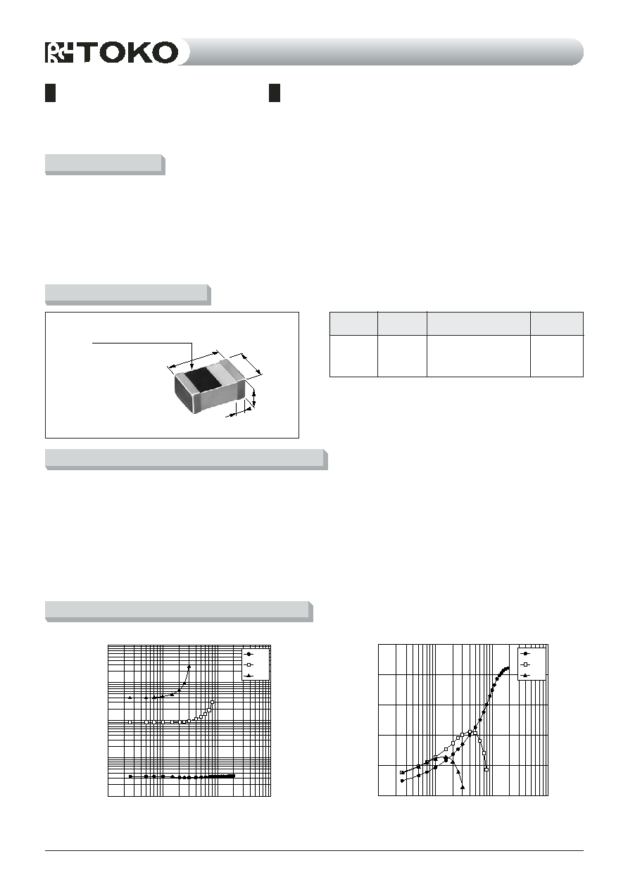
DIMENSIONS
FEATURES
ELECTRICAL CHARACTERISTICS
LL2012-FHL
Series
continued on next page
Electrode
widthA (mm)
Thickness
T (mm)
Width
W (mm)
Length
L (mm)
∑ Inductance Range
1.5~680nH (E-12 Series)
∑ Inductance Tolerance
S ;
±
0.3nH (1.5~5.6nH)
J ;
±
5% (6.8~680nH)
K ;
±
10%, (3.3~680nH)
∑ Q (Typical)
22 ~ 65 (at 800MHz)
∑ Rated Current
50~300mA
∑ L Temperature Coefficient
+ 250ppm/∞C
(for reference only)
∑ Operating Temperature Range
-
40~
+
100∞C
∑ Storage Temperature Range
-
40~
+
100∞C
∑
1.5680nH (E-12 Series
∑
S; ±0.3nH (1.55.6nH)
J ; ±% (6.8680nH)
K; ±10% (3.3680nH)
∑
Q (Typical)
2265 (at 800MHz)
∑
50300mA
∑
L ()
250ppm/
∑
-40100
∑
-40100
∑ Marking of polarity: Marking is on the upper surface of
the unit.
∑
:
2.0 ± 0.2
1.25 ± 0.2
0.6 ± 0.2 (1.5~8.2nH)
0.85 ± 0.3 (10.0~39.0nH)
1.0 ± 0.3 (47.0~100nH)
1.2 ± 0.3 (120.0~680nH)
0.5 ± 0.3
L
W
T
A
Marking of polarity (Black)
3N3
82N
R39
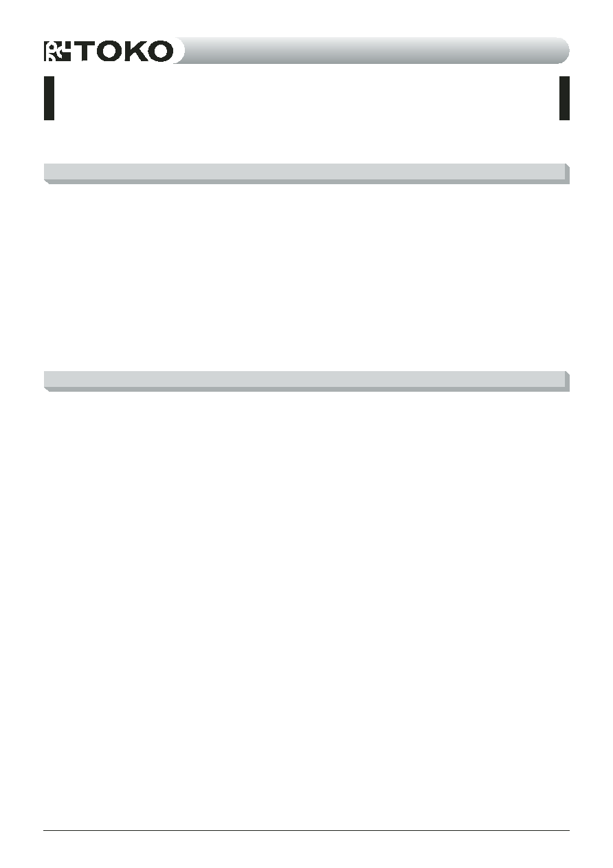
10,000
1,000
100
10
1
10
100
1,000
10,000
Inductance (nH)
Inductance vs Frequency
f(MHz)
3N3
82N
R39
80
100
60
40
20
0
10
100
1,000
10,000
Q vs Frequency
f (MHz)
Q
∑ New specifications
∑ Dual frequency standard for inductance value
∑ Supports high temperature reflow soldering (260∞C,
3 times)
∑ Surface mounting applicability (Supports both reflow and
flow soldering)
∑ High reliability (ceramic integrated structure, and terminals
plated)
∑
∑
∑
260◊
∑
∑

Multilayer Chip Inductors
3
LL2012-FHL1N5S
LL2012-FHL1N8S
LL2012-FHL2N2S
LL2012-FHL2N7S
LL2012-FHL3N3S
LL2012-FHL3N9S
LL2012-FHL4N7S
LL2012-FHL5N6S
LL2012-FHL6N8J
LL2012-FHL8N2J
LL2012-FHL10NJ
LL2012-FHL12NJ
LL2012-FHL15NJ
LL2012-FHL18NJ
LL2012-FHL22NJ
LL2012-FHL27NJ
LL2012-FHL33NJ
LL2012-FHL39NJ
LL2012-FHL47NJ
LL2012-FHL56NJ
LL2012-FHL68NJ
LL2012-FHL82NJ
LL2012-FHLR10J
LL2012-FHLR12J
LL2012-FHLR15J
LL2012-FHLR18J
LL2012-FHLR22J
LL2012-FHLR27J
LL2012-FHLR33J
LL2012-FHLR39J
LL2012-FHLR47J
LL2012-FHLR56J
LL2012-FHLR68J
continued from previous page
TOKO STANDARD PART NUMBERS
TYPE LL2012-FHLSeries
(Quantity/reel; ~39nH [4,000 PCS], 47nH~ [3,000 PCS])
1.5
1.8
2.2
2.7
3.3
3.9
4.7
5.6
6.8
8.2
10
12
15
18
22
27
33
39
47
56
68
82
100
120*
150*
180*
220*
270**
330**
390**
470**
560**
680**
4000
0.10
0.02
300
4000
0.10
0.02
300
3800
0.10
0.03
300
3600
0.10
0.03
300
3400
0.10
0.04
300
3200
0.10
0.04
300
2800
0.12
0.03
300
2800
0.15
0.05
300
2100
0.15
0.06
300
2000
0.18
0.05
300
1600
0.20
0.06
300
1350
0.22
0.07
300
1350
0.24
0.11
300
1200
0.26
0.10
300
1100
0.28
0.09
300
1100
0.30
0.12
300
1000
0.40
0.13
300
900
0.50
0.13
300
800
0.55
0.21
300
750
0.60
0.23
300
700
0.65
0.24
300
600
0.70
0.28
300
550
0.80
0.33
300
500
0.85
0.32
250
450
0.90
0.44
250
400
1.00
0.51
250
360
3.00
2.15
200
330
3.50
3.22
200
300
4.00
2.86
150
270
4.50
3.82
150
240
5.00
2.58
50
210
5.50
2.69
50
180
6.00
3.14
50
11
12
12
12
12
12
12
12
12
15
15
16
16
16
16
16
16
16
17
17
17
20
20
16*
16*
10**
10**
11**
11**
11**
11**
11**
11**
1.5 ±0.5nH
800
1.7 ±0.5nH
800
2.1 ±0.5nH
800
2.42 ±0.5nH
800
3.0 ±0.5nH
800
3.7 ±0.5nH
800
4.6 ±0.5nH
800
5.7 ±0.5nH
800
6.7
±10%
800
8.2
±10%
800
10.2
±10%
800
12.7
±10%
800
15.8
±10%
800
19.5
±10%
800
24.5
±10%
800
31.2
±10%
800
38.5
±10%
800
50.7
±10%
800
63.9
±10%
800
62.7
±10%
500
80.3
±10%
500
103
±10%
500
142
±10%
500
139
±10%
300
173
±10%
300
194
±10%
200
234
±10%
200
303
±10%
200
382
±10%
200
500
±10%
200
≠
≠
≠
≠
≠
≠
≠
≠
≠
15.3
27.5
37.5
52.0
61.5
79.3
14.0
25.0
33.9
46.6
54.0
78.4
16.7
29.5
39.9
55.0
62.6
96.4
15.5
27.5
36.8
50.8
57.8
89.0
15.4
29.0
39.2
52.6
59.2
96.4
16.0
29.7
39.7
53.4
59.7
76.8
16.5
30.4
40.9
54.3
61.0
81.0
17.0
31.3
42.1
55.2
61.0
76.9
18.7
33.3
44.6
58.1
63.9
89.7
18.5
32.2
42.4
54.8
59.5
73.2
18.9
33.7
44.4
56.9
61.5
75.7
20.5
36.5
47.5
60.8
65.9
79.8
22.1
39.5
51.5
64.2
68.2
67.9
22.9
40.7
52.9
64.9
68.4
49.3
21.6
38.0
48.6
56.8
57.4
≠
22.8
39.6
49.4
57.4
57.3
≠
23.0
39.9
49.9
55.6
54.4
≠
24.6
41.4
50.0
50.9
45.5
≠
24.8
41.8
49.5
47.4
39.4
≠
26.1
43.3
50.0
44.5
34.5
≠
25.7
41.8
46.2
33.6
18.1
≠
26.5
41.4
43.1
21.5
≠
≠
27.7
43.3
41.4
≠
≠
≠
26.4
38.2
31.0
≠
≠
≠
29.2
40.3
29.6
≠
≠
≠
28.2
33.2
≠
≠
≠
≠
25.1
32.8
≠
≠
≠
≠
23.6
28.8
≠
≠
≠
≠
26.0
28.6
≠
≠
≠
≠
25.0
21.1
≠
≠
≠
≠
25.5
≠
≠
≠
≠
≠
24.5
≠
≠
≠
≠
≠
26.5
≠
≠
≠
≠
≠
S
S
S
S
S
S
S
S
J
J
J
J
J
J
J
J
J
J
J
J
J
J
J
J
J
J
J
J
J
J
J
J
J
TOKO
part number
1800
MHz
1000
MHz
800
MHz
500
MHz
300
MHz
100
MHz
Freq.
(MHz)
Inductance & Tolerance
at 100MHz
at 800(500, 300, 200)MHz
Q Typ.
Q
Min.
100
MHz
S.R.F
(MHz)
Min.
R
DC
()
Max.
I
DC
(mA)
Max.
R
DC
()
Typ.
L
(nH)
Toler-
ance
L
(nH)
Toler-
ance
*
at 50MHz,
**
at 25MHz
∑Test Equipment & note
() ∑ L, Q
: RF Impedance Analyzer 4291A/B (Agilent), Test Fixture 16192A (Agilent)
∑ S.R.F.
: Network Analyzer 8719D (Agilent), 8720D (Agilent)
∑ RDC
: Milliohmmeter 4338A/B (Agilent)
∑ Inductance tolerance : S=
±
0.3nH, J=
±
5%
∑ Operating temperature range : -40∞C~+100∞C
∑ Storage temperature range
: -40∞C~+100∞C
Multilayer and Thick FilmChip Inductors
PRECAUTIONS
FEATURES
LL2012-FHL∑ LLP1005-FH
Series
∑
Lineup of shape series expanded from 0603 size to 2012
size.
∑
Expanded inductance range covering 1.0 nH~680 nH.
∑
Realization of product lineup that includes the addition of
B class tolerance, aiming at narrow tolerance.
∑
High frequency characteristics: Can be used over the
range 400 MHz~10 GHz.
∑
Lineup of a series that can be soldered with lead-less
solder.
∑
Lineup of a non-polarity series.
∑
Lineup of a series that has an expanded working
temperature
range of -55∞C~+125∞C.
∑
Improved L value reliability: Lineup of a series whose L
value is controlled by two frequencies (100 MHz and 800
MHz).
∑ 06032012
∑ 1.0nH680nH
∑ B±0.1nH
∑ 400MHz10GHz
∑
∑
∑ -55125
∑ 100MHz800MHzL
1. Precaution for application
1.1 The part must be pre-heated before soldering if reflow or flow
solder is applied.
The difference between pre-heat temperature and soldering
temperature must be within 150∞C.
1.2 If a solder iron is applied, the soldering process must be
completed within 3 seconds at the soldering temperature lower
than 260∞C.
The tip of the solder iron must not touch the terminal electrode
in this process.
1.3 Soldering by using an iron must be only once for the same part.
1.4 PCB mounted this part must be handled with a care to minimize
any physical stress to the part at the board assembly process.
1.5 To minimize the influence to the part, the thickness of PCB,
land dimension, and the amount of solder must be evaluated
carefully by individual application.
1.6 CFC, triethance, and isopropil used for the washing process will
not affect the part performance.
2. Precaution of storage
Storage condition is critical to maintain an optimum soldering
performance.
2.1 Environmental requirements:
Control ambient temperature at or under 40∞C and 70%RH.
Recommended use of the products within 6 months.
2.2 Influence of harmful gas:
Store the products in a place isolated from harmful gases like
sulfer and chlorine.
1.
1.1
150
1.2 260
3
1.3 11
1.4
1.5
1.6
2.
2.1
4070RH
6
2.2
LLV0603-FB ∑ LLV0603-F ∑ LL1005-FHL ∑ LL1608-FSL
Multilayer and Thick FilmChip Inductors
3
Tolerance
± 0.1nH
± 0.2nH
± 0.3nH
± 2%
± 3%
± 5%
± 10%
± 20%
Mark
B
C
S
G
T
J
K
M
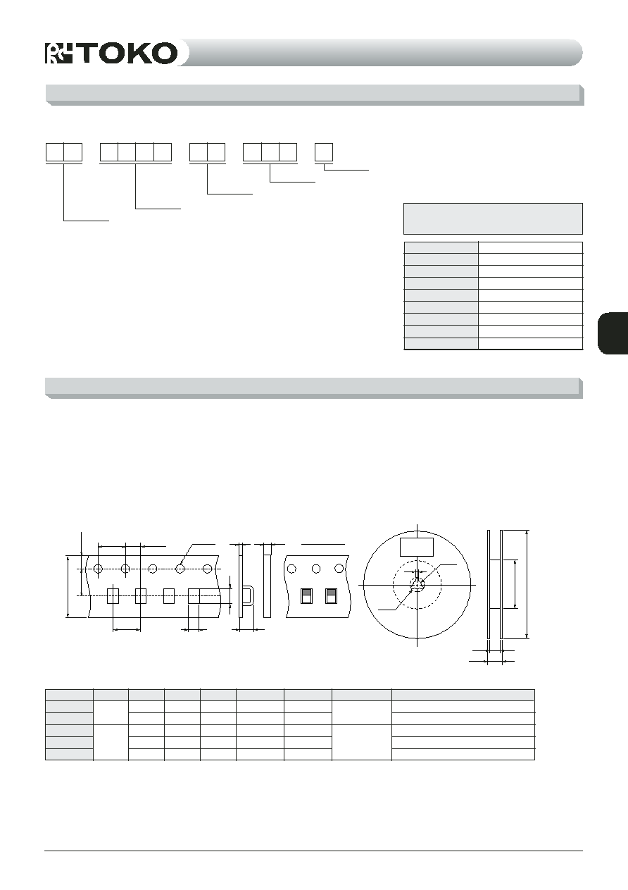
REEL PACKAGING
PART NUMBERING SYSTEM
Example
L L
1 6 0 8
F S
Tolerance
Inductance
Material
Physical Dimensions
TOKO's Type name
Unit is nH and 3 digits are used.
The value is indicated as shown below.
3nH
Example 4N7...4.7nH
33N...33nH
R27...270nH
Inductance
Tolerance for the Inductance
A
B
C
T
1
T
2
T
3
Material (Tape)
QTY (ÿ180)
Type
LL2012
LL1608
LL1005
LLP1005
LLV0603
(1) Chip's placing
Chip Inductors are packaged into 8mm width, 4 or 2mm
pitch plastic or paper tape then enclosed by cover tape.
(2) Carriage hole position
Carriage hole position is right side of tape when sealing tape
is up side.
∑ Tape dimensions (Unit: mm) (mm)
∑ Reel dimensions (Unit: mm) (mm)
(1)
8mm42mm
(2)
4
2
1.5
1.0
0.62
0.67
0.35
2.3
1.8
1.12
1.15
0.65
0.3
0.2
--
--
--
Max. 2.0
Max. 1.4
--
--
--
--
--
Max. 0.8
Max. 0.8
Max. 0.8
~39nH:4000, 47nH~3000PCS/reel
4000PCS/reel
10,000PCS/reel
10,000PCS/reel
15,000PCS/reel
Plastic
Paper
∑ Label: Customer's P/N, Q'ty, TOKO P/N, TOKO, INC.
∑
9.0 (9.5)
11.4 (13.5)
P=4.0±0.1
2.0±0.05
1.55±0.05
13
60 (100)
180 (330)
21
T
1
T
3
T
2
B
A
C
8.0
±
0.2
3.5
±
0.05
1.75
±
0.1
2
Label
( ) ¯330
Multilayer and Thick FilmChip Inductors
SOLDERING CONDITIONS
Recommended Pattern
∑ Conditions for soldering temperatures are determined as per figures below after prior confirmation that abnormalities are not
evident.
∑
b
b
c
a
2s.
250±10∞C
150±10∞C
2min.
Solder iron power
18W
Flow Soldering
Reflow Soldering
Soldering Iron
7s.
230±5∞C
80±20∞C
2min.
20s.
140~170∞C
240∞C
225∞C
2min.
80s.
Reflow soldering
a
b
c
Pattern dimensions (unit; mm)
LL2012 series
Flow soldering
1.0~1.4
0.8~1.2
0.8~1.0
1.0~1.2
0.6~1.0
0.8~1.2
0.8~1.0
0.8~1.0
0.6~0.8
0.7
0.6~0.8
0.6~0.8
0.4
0.4~0.5
0.45~0.55
0.25
0.18~0.22
0.30~0.35
Reflow soldering
Flow soldering
Reflow soldering
Reflow soldering
LL1608 series
LL1005 & LLP1005 series
LLV0603 series
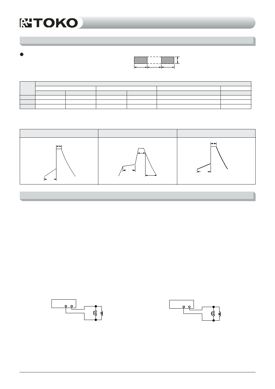
ELECTRICAL CHARACTERISTICS TEST METHOD
Test Circuit
DC RESISTANCE
TESTER
SW
INDUCTOR
SAMPLE
SW
1. INDUCTANCE, Q
∑ Test equipment
∑ Impedance analyzer:
4291A/B(Agilent):LL1005-FHL, LL1608-FSL, LL2012-FHL,
LLP1005-FH, LLV0603-FB, LLV0603-F,
∑Test fixture: 16192A(Agilent): LL1005-FHL, LL1608-FSL,
LL2012-FHL
16196B(Agilent): LLP1005-FH
16196C(Agilent): LLV0603-FB, LLV0603-F
∑ Test method
∑ Set measuring frequency read inductance and Q value.
2. RDC (DC Resistance)
∑ Test equipment
∑ 4338A/B(Agilent) or equivalent
∑ Test method
(1) Place the sample in the test terminals.
(2)
Do not place in or pull out the sample while pushing SW.
1. Q
∑
∑ 4291A/B(Agilent): LL1005-FHL, LL1608-FSL,
LL2012-FHL, LLP1005-FH,
LLV0603-FB, LLV0603-F
∑ 16192A(Agilent): LL1005-FHL, LL1608-FSL,
LL2012-FHL
16196B(Agilent): LLP1005-FH
16196C(Agilent): LLV0603-FB, LLV0603-F
∑
∑ Q
2. R
DC
()
∑
∑ 4338A/B(Agilent)
∑
(1)
(2) SW
3. Self resonance frequency (S.R.F.)
∑ Test equipment
∑ Network Analyzer: 8719D(Agilent):0.5GHz13.5GHz
8720D(Agilent):13.6GHz20.0GHz
∑ Test Method
∑ Measure the frequency at which the phase of inductive
reactance and capacitive reactance is 0.
3. S.R.F.()
∑
∑ 8719D(Agilent):0.5GHz13.5GHz
8720D(Agilent):13.6GHz20.0GHz
∑
∑
0