Key Features
l
SMT Technology
l
2:1 Input Range
l
High Efficiency up to 84 %
l
I / O Isolation 1500VDC
l
Short Circuit Protected
l
MTBF > 1,000,000 Hours
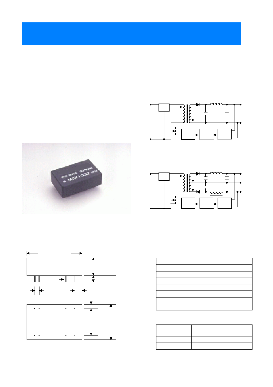
Mechanical Configuration
+Vo
PFM
Isolation
Ref.Amp
LC
Filter
+Vin
-Vin
Com.
-Vo
PFM
Isolation
Ref.Amp
LC
Filter
+Vin
-Vin
-Vo
+Vo
1.25 (31.8)
0.02 DIA
(0.5)
0.10
(2.54)
0.18
(4.6)
0.40
(10.2)
0.15 (3.8)
0.60
(15.2)
0.80
(20.3)
2
23
All dimensions typical in inches (mm). Tolerance= +/- 0.01 (+/- 0.25)
11
14
Bottom
Side
0.10 (2.54)
NC:No Connection.
+Input
+Input
22,23
Common
-Output
16
+Output
+Output
14
-Output
NC
11
Common
No Pin
9
-Input
-Input
2,3
Dual Output
Single Output
Pin
Pin Connections
12g
Weight
Non-Conductive Black Plastic
Case Material
31.8*20.3*10.2 mm
1.25*0.8*0.4 inches
Case Size
Physical Characteristics
TOTAL POWER INT'L
MIW1000 Series 2 ~ 3 Watt Wide Input Range DC/DC Converters
with
Single & Dual Output
TOTAL POWER INT'L Tel: 877-646-0900 Fax: 978-453-7395
Email: sales@total-power.com http://www.total-power.com
-1-

mW
2500
---
Internal Power Dissipation
VDC
100
-0.7
48VDC Input Models
VDC
50
-0.7
24VDC Input Models
VDC
25
-0.7
12VDC Input Models
VDC
11
-0.7
5VDC Input Models
Input Surge Voltage
( 1000 mS )
Unit.
Max.
Min.
Parameter
Absolute Maximum Ratings
Exceeding these values can damage the module.These are not continuous operating ratings.
Specifications typical at Ta=+25],resistive load,nominal input voltage,rated output current unless otherwise noted.
84
75
{10
{100
{15
MIW1047
84
75
{12.5
{125
{12
MIW1046
80
65
{25
{250
{5
MIW1045
84
75
20
200
15
MIW1044
84
75
25
250
12
MIW1043
79
66
50
500
5
MIW1042
76
10
3
55
60
600
3.3
48
( 36 ~ 72 )
MIW1041
82
152
{10
{100
{15
MIW1037
82
152
{12.5
{125
{12
MIW1036
79
132
{25
{250
{5
MIW1035
84
149
20
200
15
MIW1034
84
149
25
250
12
MIW1033
79
132
50
500
5
MIW1032
76
15
5
109
60
600
3.3
24
( 18 ~ 36 )
MIW1031
80
313
{10
{100
{15
MIW1027
80
313
{12.5
{125
{12
MIW1026
77
271
{25
{250
{5
MIW1025
82
305
20
200
15
MIW1024
82
305
25
250
12
MIW1023
78
267
50
500
5
MIW1022
74
30
20
223
60
600
3.3
12
( 9 ~ 18 )
MIW1021
75
800
{10
{100
{15
MIW1017
75
800
{12.5
{125
{12
MIW1016
72
694
{25
{250
{5
MIW1015
77
779
20
200
15
MIW1014
77
779
25
250
12
MIW1013
73
685
50
500
5
MIW1012
70
100
40
566
60
600
3.3
5
( 4.5 ~ 9 )
MIW1011
Efficiency
% (Typ.)
Reflected
Ripple
Current
mA (Typ.)
Input
Current
No Load
mA (Typ.)
Input
Current
Max. Load
mA (Typ.)
Output
Current
mA (Min.)
Output
Current
mA (Max.)
Output
Voltage
VDC
Input
voltage
VDC
Model
Number
Model Selection Guide
TOTAL POWER INT'L Tel: 877-646-0900 Fax: 978-453-7395
Email: sales@total-power.com http://www.total-power.com
-2-
TOTAL POWER INT'L
MIW1000

Free-Air Convection
Cooling
%
95
---
---
Humidity
]
+125
---
-40
Storage Temperature
]
+71
---
-25
Operating Temperature
Unit
Max.
Typ.
Min.
Conditions
Parameter
Environmental Specifications
kHz
---
300
---
Switching Frequency
pF
100
65
---
100KHz,1V
Isolation Capacitance
M[
---
---
1000
500VDC
Isolation Resistance
VDC
---
---
1500
60 Seconds
Isolation Voltage
Unit
Max.
Typ.
Min.
Conditions
Parameter
General Specification
Continuous
Output Short Circuit
%/]
{0.02
{0.01
---
Temperature Coefficient
%
{5
{3
---
Transient Response Deviation
uS
500
300
---
50% Load Step Change
Transient Recovery Time
%
---
---
120
Over Load
mV rms.
15
---
---
Ripple & Noise (20MHz)
mV P-P
100
---
---
Over Line,Load & Temp.
Ripple & Noise (20MHz)
mV P-P
60
45
---
Ripple & Noise (20MHz)
%
{0.5
{0.2
---
Io=10% to 100%
Load Regulation
%
{0.5
{0.2
---
Vin=Min. to Max.
Line Regulation
%
{1.0
{0.5
---
Dual Output Balance Load
Output Voltage Balance
%
{1.0
{0.5
---
Output Voltage Accuracy
Unit
Max.
Typ.
Min.
Conditions
Parameter
Output Specifications
Pi Filter
Input Filter
mW
2000
1000
---
Short Circuit Input Power
A
1
---
---
All Models
Reverse Polarity Input Current
34
22
---
48V Input Models
17
11
---
24V Input Models
8.5
6.5
---
12V Input Models
4
3.5
---
5V Input Models
Under Voltage Shortdown
36
24
16
48V Input Models
18
12
8
24V Input Models
9
7
4.5
12V Input Models
VDC
4.5
4
3.5
5V Input Models
Start Voltage
Unit
Max.
Typ.
Min.
Model
Parameter
Input Specifications
TOTAL POWER INT'L Tel: 877-646-0900 Fax: 978-453-7395
Email: sales@total-power.com http://www.total-power.com
-3-
TOTAL POWER INT'L
MIW1000

Typical Applications
Derating Curve
Connecting Pin Patterns
(2.54 mm / 0.1 inch grids )
Single Output
Dual Output
NOTE:
1. Specifications typical at Ta=+25],resistive load,nominal input voltage,rated output current unless otherwise noted.
2. Transient recovery time is measured to within 1% error band for a step change in output load of 50% to 100%.
3. When measure output ripple & noise,an external 0.1uF ceramic capacitor is recommended to be placed from +Vout
to -Vout (single output) and each output to common (dual output).
4. Other input and output voltage may be available,Please contact factory.
5. Specifications subject to change without notice.
135mA Slow - Blow Type
350mA Slow - Blow Type
700mA Slow - Blow Type
1500mA Slow - Blow Type
48V Input Models
24V Input Models
12V Input Models
5V Input Models
Input Fuse Selection Guide
+Out
-Out
+Vin
-Vin
Single Output
DC / DC
Converter
Load
DC Power
Source
+
-
Fuse
+Out
-Out
+Vin
-Vin
Dual Output
DC / DC
Converter
Common
Load #1
Load #2
DC Power
Source
+
-
Fuse
-25
-10
0
20
60
40
80
100
125
Output
Power
%
Ambient Temperature
O
C
Output
Power
%
20
40
60
80
100
0
20
40
60
80
100
0
-3.3% /
O
C
TOTAL POWER INT'L Tel: 877-646-0900 Fax: 978-453-7395
Email: sales@total-power.com http://www.total-power.com
-4-
TOTAL POWER INT'L
MIW1000