 | ÐлекÑÑоннÑй компоненÑ: MIW1115 | СкаÑаÑÑ:  PDF PDF  ZIP ZIP |
Äîêóìåíòàöèÿ è îïèñàíèÿ www.docs.chipfind.ru
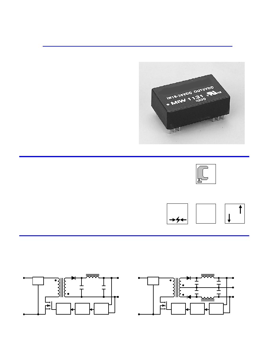
Dual Output
+Vo
PFM
Isolation
Ref.Amp
LC
Filter
+Vin
-Vin
Com.
-Vo
Single Output
PFM
Isolation
Ref.Amp
LC
Filter
+Vin
-Vin
-Vo
+Vo
Block Diagram
Wide Range
2:1
EN55022
EMI
I/O Isolation
500
VDC
Low Cost
$
MIW1100-Series power modules are low-profile
dc-dc converters that operate over input voltage ranges of
4.5-9VDC, 9-18VDC, 18-36VDC and 36-75VDC and provide
precisely regulated output voltages of 5V, 12V, 15V, {12V and
{15V.
The -40] to +71] operating temperature range makes it ideal
for data communication equipments, mobile battery driven
equipments, distributed power systems, telecommunication
equipments, mixed analog/digital subsystems, process/machine
control equipments, computer peripheral systems and industrial robot
systems.
The modules have a maximum power rating of 3W and a typical
full-load efficiency of 81%, continuous short circuit, 60mA output
ripple, built-in filtering for both input and output minimizes the need
for external filtering.
MTBF > 1,000,000 Hours
EMI Complies With EN55022 Class A
Short Circuit Protection
SMT Technology
Industry Standard Pinout
I/O Isolation 500VDC
2:1 Input Range
High Efficiency up to 81%
Key Features
Single and Dual Outputs
3 Watts 2
:1
Wide Input Range
DC/DC Converters
MIW1100
Series
TOTAL POWER INT'L

81
77
{10
{100
{15
MIW1145
81
77
{12.5
{125
{12
MIW1144
81
77
20
200
15
MIW1143
81
77
25
250
12
MIW1142
77
10
3
81
60
600
5
48
( 36 ~ 75 )
MIW1141
81
154
{10
{100
{15
MIW1135
81
154
{12.5
{125
{12
MIW1134
81
154
20
200
15
MIW1133
81
154
25
250
12
MIW1132
77
15
5
162
60
600
5
24
( 18 ~ 36 )
MIW1131
80
313
{10
{100
{15
MIW1125
80
313
{12.5
{125
{12
MIW1124
80
313
20
200
15
MIW1123
80
313
25
250
12
MIW1122
76
30
20
329
60
600
5
12
( 9 ~ 18 )
MIW1121
74
811
{10
{100
{15
MIW1115
74
811
{12.5
{125
{12
MIW1114
74
811
20
200
15
MIW1113
74
811
25
250
12
MIW1112
70
100
40
857
60
600
5
5
( 4.5 ~ 9 )
MIW1111
% (Typ.)
mA (Typ.)
mA (Typ.)
mA (Typ.)
mA
mA
VDC
VDC
@Max. Load
@No Load
@Max. Load
Min.
Max.
Efficiency
Reflected
Ripple
Current
Input Current
Output Current
Output
Voltage
Input
Voltage
Model
Number
Model Selection Guide
EN55022 Class A
Conducted EMI
Free-Air Convection
Cooling
%
95
---
Humidity
]
+125
-40
Storage Temperature
]
+90
-40
Case
Operating Temperature
]
+71
-40
Ambient
Operating Temperature
Unit
Max.
Min.
Conditions
Parameter
Environmental Specifications
Exceeding these values can damage the module. These are not continuous
operating ratings.
mW
2,500
---
Internal Power Dissipation
]
260
---
Lead Temperature (1.5mm from case for 10 Sec.)
VDC
100
-0.7
48VDC Input Models
VDC
50
-0.7
24VDC Input Models
VDC
25
-0.7
12VDC Input Models
VDC
11
-0.7
5VDC Input Models
Input Surge Voltage
( 1000 mS )
Unit
Max.
Min.
Parameter
Note :
1. Specifications typical at Ta=+25], resistive load,
nominal input voltage, rated output current unless
otherwise noted.
2. Transient recovery time is measured to within 1%
error band for a step change in output load of 75%
to 100%.
3. Ripple & Noise measurement bandwidth is 0-20
MHz.
4. These power converters require a minimum
output loading to maintain specified regulation.
5. Operation under no-load conditions will not
damage these devices; however they may not
meet all listed specifications.
6. All DC/DC converters should be externally fused at
the front end for protection.
7. Other input and output voltage may be available,
please contact factory.
8. Specifications subject to change without notice.
Absolute Maximum Ratings
MIW1100 Series

K Hours
---
---
1000
MIL-HDBK-217F @ 25], Ground Benign
MTBF
KHz
---
300
---
Switching Frequency
pF
500
---
---
100KHz,1V
Isolation Capacitance
M[
---
---
1000
500VDC
Isolation Resistance
VDC
---
---
550
Flash Tested for 1 Second
Isolation Test Voltage
VDC
---
---
500
60 Seconds
Isolation Voltage
Unit
Max.
Typ.
Min.
Conditions
Parameter
General Specifications
Continuous
Output Short Circuit
%/]
{0.02
{0.01
---
Temperature Coefficient
%
{5
{3
---
Transient Response Deviation
uS
500
300
---
25% Load Step Change
Transient Recovery Time
%
---
---
120
Over Power Protection
mV rms.
15
---
---
Ripple & Noise (20MHz)
mV P-P
100
---
---
Over Line,Load & Temp
Ripple & Noise (20MHz)
mV P-P
60
45
---
Ripple & Noise (20MHz)
%
{0.5
{0.2
---
Io=10% to 100%
Load Regulation
%
{0.5
{0.2
---
Vin=Min. to Max.
Line Regulation
%
{2.0
{0.5
---
Dual Output Balance Load
Output Voltage Balance
%
{2.0
{0.5
---
Output Voltage Accuracy
Unit
Max.
Typ.
Min.
Conditions
Parameter
Output Specifications
Pi Filter
Input Filter
mW
1500
1000
---
Short Circuit Input Power
A
1
---
---
All Models
Reverse Polarity Input Current
34
22
---
48V Input Models
17
11
---
24V Input Models
8.5
6.5
---
12V Input Models
4
3.5
---
5V Input Models
Under Voltage Shortdown
36
24
16
48V Input Models
18
12
8
24V Input Models
9
7
4.5
12V Input Models
VDC
4.5
4
3.5
5V Input Models
Start Voltage
Unit
Max.
Typ.
Min.
Model
Parameter
Input Specifications
Note: # For each output .
uF
1000
1000
2000
2000
2000
Maximum Capacitive Load
Unit
{15V #
{12V #
15V
12V
5V
Models by Vout
Capacitive Load
MIW1100 Series
135mA Slow - Blow Type
350mA Slow - Blow Type
700mA Slow - Blow Type
1500mA Slow - Blow Type
48V Input Models
24V Input Models
12V Input Models
5V Input Models
Input Fuse Selection Guide
Vin ( VDC )
10uS
150
140
130
120
110
100
90
80
70
60
100uS
1mS
10mS
100mS
50
40
30
20
10
0
48VDC Input Models
24VDC Input Models
12VDC Input Models
5VDC Input Models
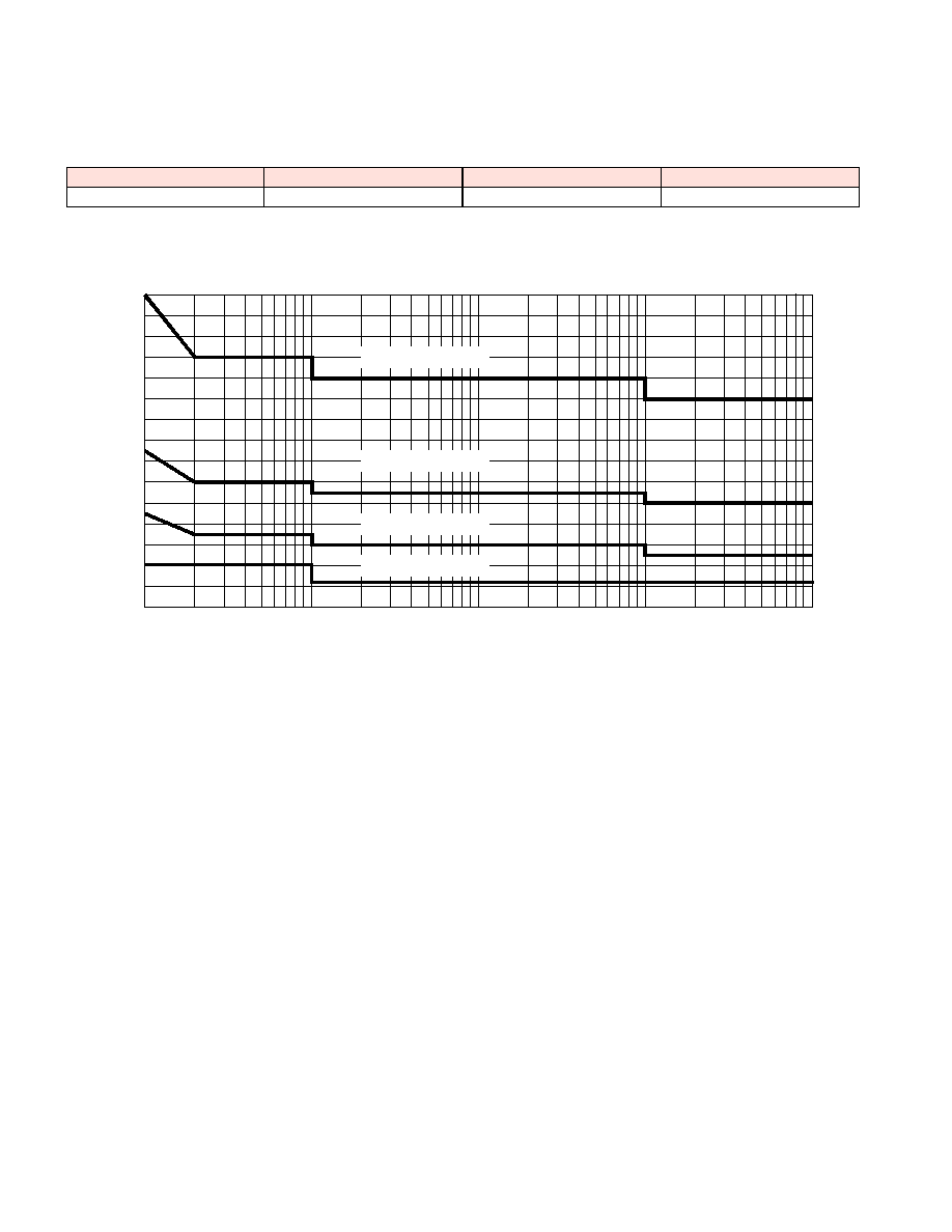
Input Voltage Transient Rating
MIW1100 Series
Derating Curve
]
Ambient Temperature
Output Power (%)
0
20
40
60
80
100
-40
50
60
80
100
110
90
70
400LFM
200LFM
100LFM
Natural
convection
Efficiency vs Output Load ( Dual Output )
Efficiency vs Output Load ( Single Output )
20
30
40
50
60
70
80
90
Load Current (%)
Efficiency (%)
100
60
40
20
10
80
20
30
40
50
60
70
80
90
Load Current (%)
Efficiency (%)
100
60
40
20
10
80
Efficiency vs Input Voltage ( Dual Output )
Efficiency vs Input Voltage ( Single Output )
Input Voltage (V)
Nom
Low
High
60
70
80
90
100
Efficiency (%)
Input Voltage (V)
Nom
Low
High
60
70
80
90
100
Efficiency (%)
MIW1100 Series