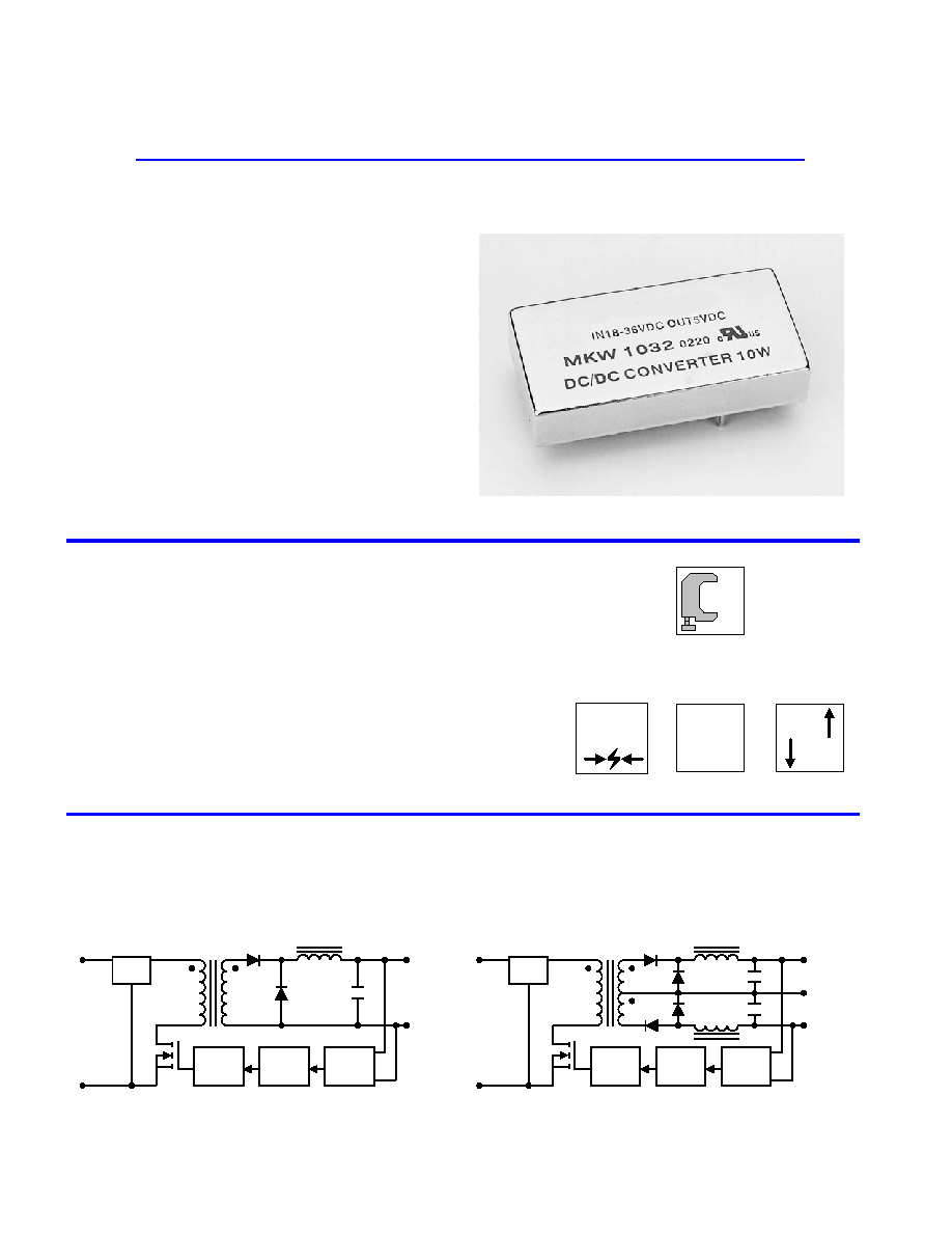
Dual Output
+Vo
PWM
Isolation
Ref.Amp
LC
Filter
+Vin
-Vin
Com.
-Vo
Single Output
PWM
Isolation
Ref.Amp
LC
Filter
+Vin
-Vin
-Vo
+Vo
Block Diagram
Wide Range
2:1
EN55022
EMI
I/O Isolation
1500
VDC
Low Cost
$
MKW1000 series of DC/DC converters, comprising 24
different models, is designed for a wide range of applications
including data communication equipments, mobile battery driven
equipments, distributed power systems, telecommunication
equipments, mixed analog/digital subsystems, process/machine
control equipments,computer peripheral systems and industrial robot
systems.
Packing up to 10W of power into a 2 x 1 x 0.4 inch package, with
efficiencies as high as 83%, the MKW1000 has wide input ranges of
9-18VDC, 18-36VDC and 36-75VDC and is available in output
voltages of 3.3V, 5V, 12V, 15V, 24V, {5V, {12V and {15V.
Other feathers include continuous short circuit protection,
six-side shielded case and EN55022 level A conducted noise
compliance minimize design-in time, cost and eliminate the need for
external components.
MTBF > 700,000 Hours
Six-Side Shielded Case
EMI Complies With EN55022 Class A
Industry Standard Pinout
Short Circuit Protection
SMT Technology
I/O Isolation 1500VDC
2:1 Input Range
High Efficiency up to 83%
Key Features
Single and Dual Outputs
10 Watts 2:1
Wide Input Range
DC/DC Converters
TOTAL POWER INT'L
TOTAL POWER INT'L Tel: 877-646-0900 Fax: 978-453-7395
Email: sales@total-power.com http://www.total-power.com
-1-

83
251
{17
{333
{15
MKW1048
83
251
{21
{416
{12
MKW1047
81
257
{50
{1000
{5
MKW1046
83
251
21
416
24
MKW1045
83
252
34
670
15
MKW1044
82
253
42
830
12
MKW1043
80
260
100
2000
5
MKW1042
76
12
10
217
120
2400
3.3
48
( 36 ~ 75 )
MKW1041
82
507
{17
{333
{15
MKW1038
82
507
{21
{416
{12
MKW1037
80
521
{50
{1000
{5
MKW1036
83
501
21
416
24
MKW1035
82
511
34
670
15
MKW1034
82
506
42
830
12
MKW1033
78
534
100
2000
5
MKW1032
76
25
20
434
120
2400
3.3
24
( 18 ~ 36 )
MKW1031
80
1041
{17
{333
{15
MKW1028
81
1027
{21
{416
{12
MKW1027
78
1068
{50
{1000
{5
MKW1026
81
1027
21
416
24
MKW1025
80
1047
34
670
15
MKW1024
80
1038
42
830
12
MKW1023
77
1082
100
2000
5
MKW1022
72
50
30
917
120
2400
3.3
12
( 9 ~ 18 )
MKW1021
% (Typ.)
mA (Typ.)
mA (Typ.)
mA (Typ.)
mA
mA
VDC
VDC
@Max. Load
@No Load
@Max. Load
Min.
Max.
Efficiency
Reflected
Ripple
Current
Input Current
Output Current
Output
Voltage
Input
Voltage
Model
Number
Model Selection Guide
EN55022 Class A
Conducted EMI
Free-Air Convection
Cooling
%
95
---
Humidity
]
+125
-40
Storage Temperature
]
+90
-40
Case
Operating Temperature
]
+71
-40
Ambient
Operating Temperature
Unit
Max.
Min.
Conditions
Parameter
Environmental Specifications
Exceeding these values can damage the module. These are not continuous
operating ratings.
mW
5,000
---
Internal Power Dissipation
]
260
---
Lead Temperature (1.5mm from case for 10 Sec.)
VDC
100
-0.7
48VDC Input Models
VDC
50
-0.7
24VDC Input Models
VDC
25
-0.7
12VDC Input Models
Input Surge Voltage
( 1000 mS )
Unit
Max.
Min.
Parameter
Note :
1. Specifications typical at Ta=+25], resistive load,
nominal input voltage, rated output current unless
otherwise noted.
2. Transient recovery time is measured to within 1%
error band for a step change in output load of 75%
to 100%.
3. Ripple & Noise measurement bandwidth is 0-20
MHz.
4. These power converters require a minimum
output loading to maintain specified regulation.
5. Operation under no-load conditions will not
damage these devices; however they may not
meet all listed specifications.
6. All DC/DC converters should be externally fused at
the front end for protection.
7. Other input and output voltage may be available,
please contact factory.
8. Specifications subject to change without notice.
Absolute Maximum Ratings
TOTAL POWER INT'L Tel: 877-646-0900 Fax: 978-453-7395
Email: sales@total-power.com http://www.total-power.com
-2-

K Hours
---
---
700
MIL-HDBK-217F @ 25], Ground Benign
MTBF
KHz
340
300
260
Switching Frequency
pF
470
150
---
100KHz,1V
Isolation Capacitance
M[
---
---
1000
500VDC
Isolation Resistance
VDC
---
---
1650
Flash Tested for 1 Seconds
Isolation Test Voltage
VDC
---
---
1500
60 Seconds
Isolation Voltage
Unit
Max.
Typ.
Min.
Conditions
Parameter
General Specifications
Continuous
Output Short Circuit
%/]
{0.02
{0.01
---
Temperature Coefficient
%
{4
{2
---
Transient Response Deviation
uS
300
150
---
25% Load Step Change
Transient Recovery Time
%
---
---
120
Over Power Protection
mV rms.
15
---
---
Ripple & Noise (20MHz)
mV P-P
100
---
---
Over Line,Load & Temp
Ripple & Noise (20MHz)
mV P-P
75
50
---
Ripple & Noise (20MHz)
%
{0.5
{0.1
---
Io=10% to 100%
Load Regulation
%
{0.3
{0.1
---
Vin=Min. to Max.
Line Regulation
%
{2.0
{0.5
---
Dual Output Balance Load
Output Voltage Balance
%
{1.0
{0.5
---
Output Voltage Accuracy
Unit
Max.
Typ.
Min.
Conditions
Parameter
Output Specifications
Pi Filter
Input Filter
mW
4500
3500
---
Short Circuit Input Power
A
2
---
---
All Models
Reverse Polarity Input Current
34
29
25
48V Input Models
17
15
13
24V Input Models
8.5
8
7
12V Input Models
Under Voltage Shortdown
36
33
30
48V Input Models
18
17
15
24V Input Models
VDC
9
8.5
8
12V Input Models
Start Voltage
Unit
Max.
Typ.
Min.
Model
Parameter
Input Specifications
Note: # For each output .
uF
470
470
470
2200
2200
2200
2200
2200
Maximum Capacitive Load
Unit
{15V #
{12V #
{5V #
24V
15V
12V
5V
3.3V
Models by Vout
Capacitive Load
750mA Slow - Blow Type
1500mA Slow - Blow Type
3000mA Slow - Blow Type
48V Input Models
24V Input Models
12V Input Models
Input Fuse Selection Guide
Vin ( VDC )
10uS
150
140
130
120
110
100
90
80
70
60
100uS
1mS
10mS
100mS
50
40
30
20
10
0
48VDC Input Models
24VDC Input Models
12VDC Input Models
Input Voltage Transient Rating
Derating Curve
]
Ambient Temperature
Output Power (%)
0
20
40
60
80
100
-40
50
60
80
100
110
90
70
400LFM
200LFM
100LFM
Natural
convection
Efficiency vs Output Load ( Dual Output )
Efficiency vs Output Load ( Single Output )
20
30
40
50
60
70
80
90
Load Current (%)
Efficiency (%)
100
60
40
20
10
80
20
30
40
50
60
70
80
90
Load Current (%)
Efficiency (%)
100
60
40
20
10
80
Efficiency vs Input Voltage ( Dual Output )
Efficiency vs Input Voltage ( Single Output )
50
60
70
80
90
100
Efficiency (%)
Input Voltage (V)
Nom
Low
High
50
60
70
80
90
100
Efficiency (%)
Input Voltage (V)
Nom
Low
High