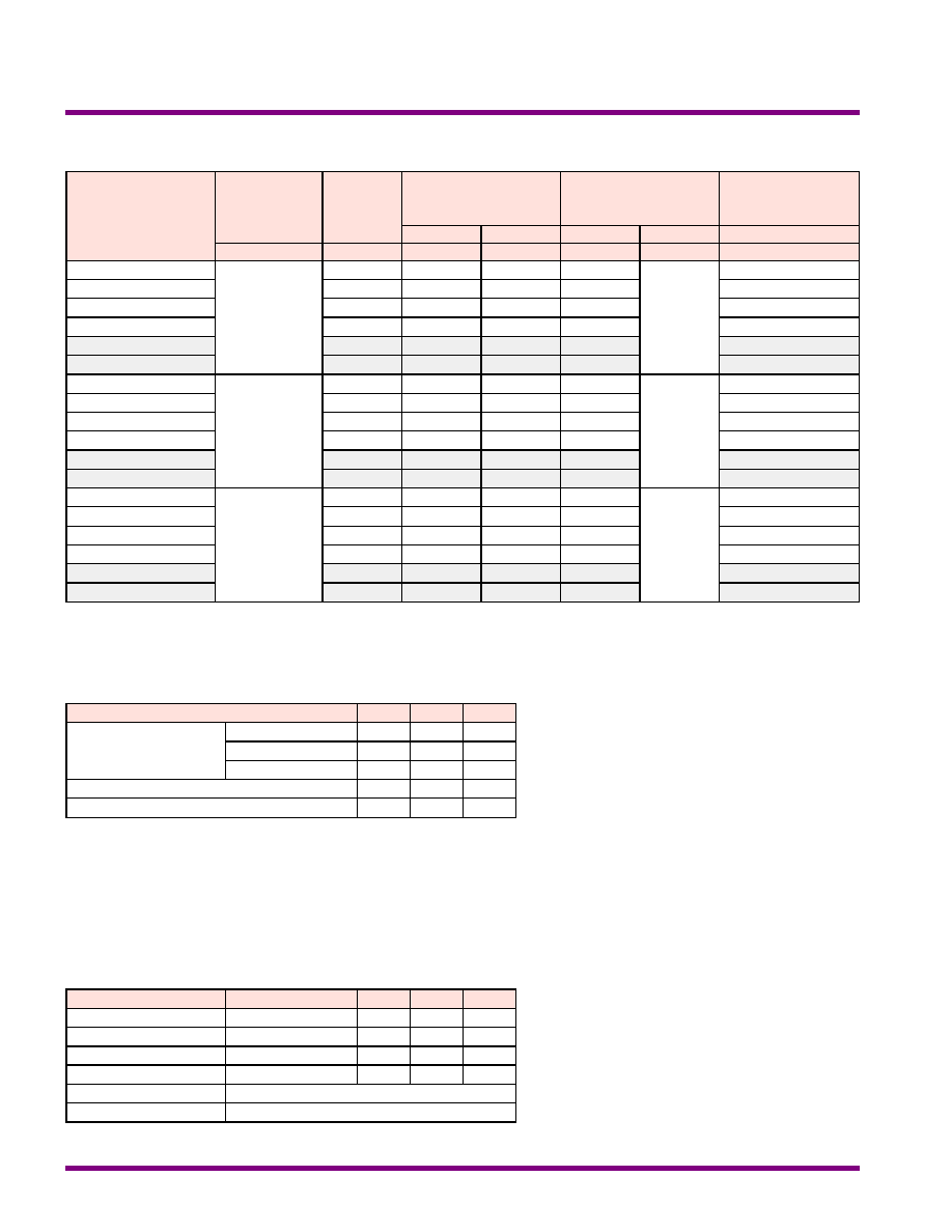
Dual Output
+Vo
PWM
Isolation
Ref.Amp
LC
Filter
+Vin
-Vin
Com.
-Vo
Single Output
PWM
Isolation
Ref.Amp
LC
Filter
+Vin
-Vin
-Vo
+Vo
Block Diagram
Remote on/off
EN55022
EMI
I/O Isolation
1500
VDC
More Power
High
Power
Density
Wide Range
2:1
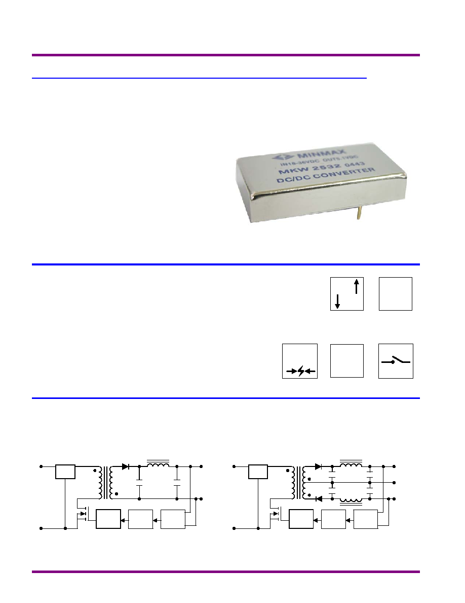
Minmax's MKW2500 series, comprising 18 different models, has
been conceived as an applications specific range of DC/DC
converters, specially addressing data communication equipments,
mobile battery driven equipments, distributed power systems,
telecommunication equipments, mixed analog/digital subsystems,
process/machine control equipments, computer peripheral systems
and industrial robot systems.
Packing up to 15W of power into a 2 x 1 x 0.4 inch package, with
efficiency as high as 86%, the MKW2500 has wide input ranges of
9-18VDC, 18-36VDC and 36-75VDC, and is available in output
voltages of 3.3V, 5.1V, 12V, 15V, {12V and {15V.
Other feathers include continuous short circuit protection, remote
on/off,six-side shieled case and EN55022 level A conducted noise
compliance minimize design-in time,cost and eliminate the need for
external components.
MTBF > 700,000 Hours
Remote on/off Control (Optional)
(Only For MKW2500A Series)
EMI Complies With EN55002 Class A
Six-Side Shielded Case
Industry Standard Pinout
Short Circuit Protected
I / O Isolation 1500VDC
2:1 Input Range
High Efficiency up to 86%
Key Features
Single and Dual Outputs
15 Watts 2 :1 Wide Input Range DC/DC Converters
MKW2500 / MKW2500A Series
2004/REV:4
MINMAX
1
86
363
{50
{500
{15
MKW2547
86
363
{62.5
{625
{12
MKW2546
86
363
100
1000
15
MKW2544
86
363
125
1250
12
MKW2543
82
382
295
2950
5.1
MKW2542
78
10
264
300
3000
3.3
48
( 36 ~ 75 )
MKW2541
86
726
{50
{500
{15
MKW2537
86
726
{62.5
{625
{12
MKW2536
86
726
100
1000
15
MKW2534
86
726
125
1250
12
MKW2533
82
764
295
2950
5.1
MKW2532
78
20
528
300
3000
3.3
24
( 18 ~ 36 )
MKW2531
86
1452
{50
{500
{15
MKW2527
86
1452
{62.5
{625
{12
MKW2526
86
1452
100
1000
15
MKW2524
86
1452
125
1250
12
MKW2523
82
1529
295
2950
5.1
MKW2522
78
30
1056
300
3000
3.3
12
( 9 ~ 18 )
MKW2521
% (Typ.)
mA (Typ.)
mA (Typ.)
mA
mA
VDC
VDC
@Max. Load
@No Load
@Max. Load
Min.
Max.
Efficiency
Input Current
Output Current
Output
Voltage
Input
Voltage
Model Number
Model Selection Guide
Six-Side Shielded Metal Case
RFI
Free-Air Convection
Cooling
%
95
---
Humidity
]
+125
-50
Storage Temperature
]
+100
-40
Case
Operating Temperature
]
+60
-40
Ambient
Operating Temperature
Unit
Max.
Min.
Conditions
Parameter
Environmental Specifications
Exceeding these values can damage the module.These are not continuous
operating ratings.
mW
5,000
---
Internal Power Dissipation
]
260
---
Lead Temperature (1.5mm from case for 10 Sec.)
VDC
100
-0.7
48VDC Input Models
VDC
50
-0.7
24VDC Input Models
VDC
25
-0.7
12VDC Input Models
Input Surge Voltage
( 1000 mS )
Unit
Max.
Min.
Parameter
Note :
1. Specifications typical at Ta=+25], resistive load,
nominal input voltage, rated output current unless
otherwise noted.
2. Transient recovery time is measured to within 1%
error band for a step change in output load of 75%
to 100%.
3. Ripple & Noise measurement bandwidth is 0-20
MHz.
4. These power converters require a minimum
output loading to maintain specified regulation.
5. Operation under no-load conditions will not
damage these devices; however they may not
meet all listed specifications.
6. All DC/DC converters should be externally fused
at the front end for protection.
7. Other input and output voltage may be available,
please contact factory.
8.To order the converter with Remote on/off function
,please add suffix - RC ( EX : MK2521-RC )
9. An optional internal filter is available. When the
filter is added, the MKW2500 will meet
EN55022-A. Add the suffix " A" to the model
number, e.g. MKW2521A.
10. Specifications subject to change without notice.
Absolute Maximum Ratings
MKW2500 / MKW2500A Series
2
MINMAX
2004/REV:4

Pi Filter
Input Filter
mW
3500
---
---
Short Circuit Input Power
A
1
---
---
All Models
Reverse Polarity Input Current
34
29
25
48V Input Models
17
15
13
24V Input Models
8.5
8
7
12V Input Models
Under Voltage Shortdown
36
33
30
48V Input Models
18
17
15
24V Input Models
VDC
9
8.5
8
12V Input Models
Start Voltage
Unit
Max.
Typ.
Min.
Model
Parameter
Input Specifications
Continuous
Output Short Circuit
%/]
{0.02
{0.01
---
Temperature Coefficient
%
{4
{2
---
Transient Response Deviation
uS
500
300
---
25% Load Step Change
Transient Recovery Time
%
---
---
120
Over Power Protection
mV rms.
15
---
---
Ripple & Noise (20MHz)
mV P-P
100
---
---
Over Line,Load & Temp
Ripple & Noise (20MHz)
mV P-P
80
55
---
Ripple & Noise (20MHz)
%
{1.0
{0.5
---
Io=10% to 100%
Load Regulation
%
{0.5
{0.1
---
Vin=Min. to Max.
Line Regulation
%
{2.0
{0.5
---
Dual Output Balance Load
Output Voltage Balance
%
{2.0
{1.0
---
Output Voltage Accuracy
Unit
Max.
Typ.
Min.
Conditions
Parameter
Output Specifications
K Hours
---
---
700
MIL-HDBK-217F @ 25], Ground Benign
MTBF
KHz
400
330
290
Switching Frequency
pF
1500
1200
---
100KHz,1V
Isolation Capacitance
M[
---
---
1000
500VDC
Isolation Resistance
VDC
---
---
1650
Flash Tested for 1 Second
Isolation Test Voltage
VDC
---
---
1500
60 Seconds
Isolation Voltage
Unit
Max.
Typ.
Min.
Conditions
Parameter
General Specifications
Referenced to Negative Input
Control Common
mA
-1
---
---
Control Input Current ( off )
uA
50
---
---
Control Input Current ( on )
mA
10
---
---
Standby Input Current
VDC
0.8
---
-0.7
Supply Off
2.5 to 5.5VDC or Open Circuit
Supply On
Unit
Max.
Typ.
Min.
Conditions
Parameter
Remote On/Off Control
MKW2500 / MKW2500A Series
2004/REV:4
MINMAX
3

Note: # For each output .
uF
220
220
470
470
470
470
Maximum Capacitive Load
Unit
{15V #
{12V #
15V
12V
5.1V
3.3V
Models by Vout
Capacitive Load
750mA Slow - Blow Type
1500mA Slow - Blow Type
3000mA Slow - Blow Type
48V Input Models
24V Input Models
12V Input Models
Input Fuse Selection Guide
Vin ( VD
C
)
10uS
150
140
130
120
110
100
90
80
70
60
100uS
1mS
10mS
100mS
50
40
30
20
10
0
48VDC Input Models
24VDC Input Models
12VDC Input Models
Input Voltage Transient Rating
MKW2500 / MKW2500A Series
4
MINMAX
2004/REV:4

Derating Curve
]
Ambient Temperature
O
u
t
p
u
t
P
o
w
e
r (%
)
0
20
40
60
80
100
-40
50
60
80
100
110
90
70
400LFM
200LFM
100LFM
Natural
convection
Efficiency vs Output Load ( Dual Output )
Efficiency vs Output Load ( Single Output )
30
40
50
60
70
80
90
100
Load Current (%)
Efficiency (%)
100
60
40
20
10
80
30
40
50
60
70
80
90
Load Current (%)
Ef
f
i
ci
ency (
%
)
100
60
40
20
10
80
Efficiency vs Input Voltage ( Dual Output )
Efficiency vs Input Voltage ( Single Output )
50
60
70
80
90
100
Input Voltage (V)
E
f
f
i
ciency (
%
)
Nom
Low
High
50
60
70
80
90
100
Input Voltage (V)
E
f
f
i
ci
ency (
%
)
Nom
Low
High
MKW2500 / MKW2500A Series
2004/REV:4
MINMAX
5