 | –≠–ª–µ–∫—Ç—Ä–æ–Ω–Ω—ã–π –∫–æ–º–ø–æ–Ω–µ–Ω—Ç: TMC428-A | –°–∫–∞—á–∞—Ç—å:  PDF PDF  ZIP ZIP |
TMC428 DATASHEET (V. 2.00 / November 12, 2003)
1
Copyright © 2000≠2003 TRINAMIC Microchips GmbH
TMC428 ≠ DATASHEET
Intelligent Triple Stepper Motor Controller with
Serial Peripheral Interfaces
TRINAMIC
Æ
Microchips GmbH
Deelboegenkamp 4c
D ≠ 22297 Hamburg
GERMANY
P +49 - (0) 40 - 51 48 06 - 0
F +49 - (0) 40 - 51 48 06 - 60
www.trinamic.com
info@trinamic.com
1 Features
The TMC428 is a miniaturized high performance stepper motor controller. It controls up to three 2-
phase stepper motors. All motors can operate independently. The TMC428 allows up to 6 bit microstep
resolution≠ corresponding to 64 microsteps per full step ≠individually selectable for each motor. Once
initialized, it performs all real time critical tasks autonomously based on target positions and velocities,
which may be altered on-the-fly. So, an inexpensive microcontroller together with the TMC428 forms a
complete motion control system. The microcontroller is free to do application specific interfacing and
high level control functions. Both, the communication with the microcontroller and with one to three
daisy chained stepper motor drivers take place via two separate 4 wire serial peripheral interfaces. The
TMC428 directly connects to SPI
TM*
smart power stepper motor drivers.
∑ Controls up to three 2-phase stepper motors
∑ Serial 4-wire interface for µC with easy-to-use protocol
∑ Configurable interface for SPI
TM
motor drivers
∑ Different types of SPI
TM
stepper motor driver chips may be mixed within a single daisy chain
∑ Communication on demand minimizes traffic to the SPI
TM
stepper motor driver chain
∑ Programmable SPI
TM
data rates up to 1 Mbit/s
∑ Wide range for clock frequency ≠ can use CPU clock up to 16 MHz
∑ Internal 24 bit wide position counters
∑ Full step frequencies up to 20 kHz
∑ Read-out facility for actual motion parameters (position, velocity, acceleration) and driver status
∑ Individual microstep resolution of {64, 32, 16, 8, 4, 2, 1} microsteps via built-in sequencer
∑ Programmable 6 bit microstep table with up to 64 entries for a quarter sine-wave period
∑ Built-in ramp generators for autonomous positioning and speed control
∑ On-the-fly change of target motion parameters (like position, velocity, acceleration)
∑ Automatic acceleration dependent current control (power boost)
∑ Low power operation: Only 1.25 mA @ 4 MHz (typ.)
∑ Power down mode with transparent wake-up for normal operation
∑ 3.3V or 5V operation with CMOS / TTL compatible IOs (all inputs Schmitt-Trigger)
∑ Available in ultra small 16 pin SSOP package, 24 pin SOP package, and 20 pin DIL package
*
SPI is Trademark of Motorola, Inc.

TMC428 DATASHEET (V. 2.00 / November 12, 2003)
2
Copyright © 2000≠2003 TRINAMIC Microchips GmbH
Life support policy
TRINAMIC Microchips GmbH does not authorize
or warrant any of its products for use in life
support systems, without the specific written
consent of TRINAMIC Microchips GmbH.
Life support systems are equipment intended to
support or sustain life, and whose failure to
perform, when properly used in accordance with
instructions provided, can be reasonably
expected to result in personal injury or death.
© 2000≠2003, TRINAMIC Microchips GmbH
Information given in this data sheet is believed to
be accurate and reliable. However no
responsibility is assumed for the consequences
of its use nor for any infringement of patents or
other rights of third parties which may result form
its use.
Specifications subject to change without notice.
TMC428 DATASHEET (V. 2.00 / November 12, 2003)
3
Copyright © 2000≠2003 TRINAMIC Microchips GmbH
2 General
Description
The TMC428 is a miniaturized high performance stepper motor controller with a unique price /
performance ratio for both, high volume automotive and for demanding industrial motion control
applications. Once initialized, the TMC428 controls up to three 2-phase stepper motors. Its low price
makes it attractive also for applications, where only one or two stepper motors have to be controlled
simultaneously.
The TMC428 performs all real time critical tasks autonomously. Thus a low cost microcontroller is
sufficient to perform the tasks of initialization, application specific interfacing, and to specify target
positions and velocities. The TMC428 allows on-the-fly change of all motion target parameters also
during motion. Any other parameter may be changed at any time≠ also during motion ≠which does not
make sense in any case, but this uniform access to any TMC428 register simplifies application
programming. Read-back option for all internal registers simplifies programming. With its internal
position counters , the TMC428 can perform up to 2
23
steps respectively microsteps fully independent
from the microcontroller. The step resolution≠ individually programmable for each stepper motor ≠
ranges from full step (1 `'microstep'' is one fullstep), half step (2 `'microsteps'' per fullstep), up to 6 bit
microstepping (64 microsteps per full step) for precise positioning and noiseless stepper motor rotation
(Table 8-8, page 25). Optionally, the microstep table≠ common for all motors ≠can be adapted to motor
characteristics to further reduce torque ripple.
The TMC428 has got serial interfaces for communication with the microcontroller and for the stepper
motor drivers. The serial interface for the microcontroller uses a fixed length of 32 bits with a simple
protocol, directly connecting to SPI
TM
interfaces. The serial interface to the stepper motor drivers is
flexibly configurable for different types≠ even from different vendors ≠with up to 64 bit length for the
SPI daisy chain. TRINAMIC Microchips smart power stepper motor drivers TMC236, TMC239 and
TMC246, TMC249 perfectly fit to the TMC428. Without additional hardware, drivers with same serial
interface polarities of chip select and clock signals may be mixed in a single chain. To mix drivers with
different serial interface polarities, additional inverters (e.g. 74HC04, 74HC14) are required. For those
driver chips without serial data output, two additional variants of the TMC428 with two additional chip
select outputs are available. The TMC428 sends data to the driver chain on demand only, which
minimizes the interface traffic and reduces the power consumption.
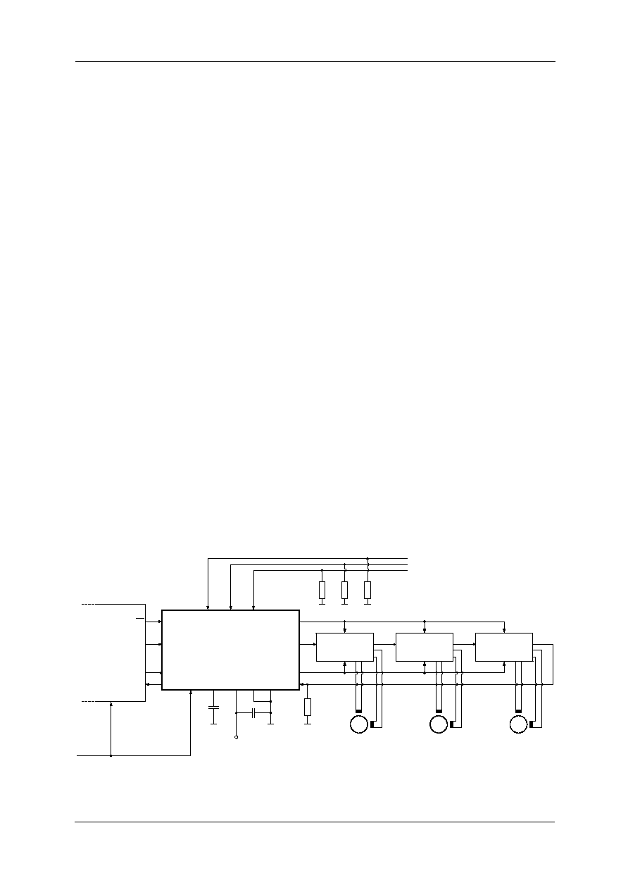
10K
SCK_S
SDO_S
SDI_S
nSCS_S
SDO
CSN
SDI
SCK
SDO
CSN
SDI
SCK
SDO
CSN
SDI
SCK
TMC23x / TMC24x
TMC23x / TMC24x
TMC23x / TMC24x
REF2
REF3
REF1
TEST
GND
µC
SCK
MOSI
MISO
SS
SDI_C
nSCS_C
SCK_C
SDO_C
CLK
CLK
V5
V33
470
nF
+5 V
1K
1K
Reference Switch Inputs
(active high)
SM#3
SM#2
SM#1
TMC428-I /
TMC428-A
1K
100 nF
*For details concerning electrical connections of
the TMC236 / TMC239 / TMC246 / TMC249
refer to its datasheet.
*
*
*
Note: output SDO_C will
nerver be high impedance
Figure 2-1: TMC428 application environment with TMC428 in SSOP16 package
TMC428 DATASHEET (V. 2.00 / November 12, 2003)
4
Copyright © 2000≠2003 TRINAMIC Microchips GmbH
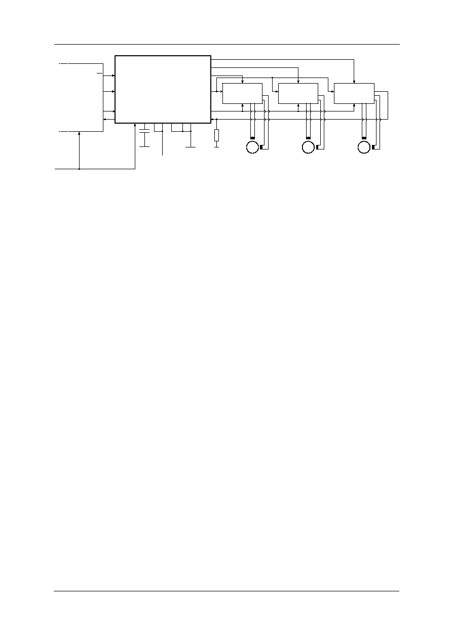
10K
SCK_S
SDO_S
SDI_S
nSCS_S
nSCS
SDI
SCK
nSCS
SDI
SCK
nSCS
SDI
SCK
Driver
w/o SDO
Driver
w/o SDO
REF2
REF3
REF1
TEST
GND
µC
SCK
MOSI
MISO
SS
SDI_C
nSCS_C
SCK_C
SDO_C
CLK
CLK
V5
V33
470 nF
+5 V
SM#3
SM#2
SM#1
TMC428-PI24 /
TMC428-DI20
nSCS2
nSCS3
SDO
V5
GND
Note: output SDO_C will
nerver be high impedance
Driver
w/o SDO
Figure 2-2: Usage of drivers without serial data output (SDO) with TMC428 in larger packages
2.1 Step
Frequencies
The maximum SPI
TM
data rate is the clock frequency divided by 16. The maximum step frequency
depends on the total length of the datagrams sent to the SPI
TM
stepper motor driver chain. At a clock
frequency of 16 MHz, with a daisy chain of three SPI
TM
stepper motor drivers of 16 bit datagram length
each, the maximum full step frequency is 16 MHz / 16 / ( 3 * 16 ). This is approximately 20 kHz and
that is much higher than needed for typical stepper motors. But, the microstep rate may be higher,
even if the stepper motor driver does not see all microsteps due to SPI
TM
data rate limit, as long as the
number of skipped microsteps is less than a full step. In this respect, one should remember, that at
high step rates≠ respectively pulse rates ≠the differences between microstepping and full step
excitation vanishes.
2.2 Modes of Motion
The TMC428 has four different modes of motion, programmable individually for each stepper motor,
named RAMPMODE, SOFTMODE, VELOCITYMODE, and HOLDMODE. For positioning applications
the RAMPMODE is most suitable, whereas for constant velocity applications the VELOCITYMODE is.
In RAMPMODE, the user just sets the position and the TMC428 calculates a trapezoidal velocity profile
and drives autonomously to the target position. During motion, the position may be altered arbitrarily.
The SOFTMODE is similar to the RAMPMODE, but the decrease of the velocity during deceleration is
done with a soft, exponentially shaped velocity profile. In VELOCITYMODE, a target velocity is set by
the user and the TMC428 takes into account user defined limits of velocity and acceleration. In
HOLDMODE, the user sets target velocities, but the TMC428 ignores any limits of velocity and
acceleration, to realize arbitrary velocity profiles, controlled completely by the user. The TMC428 has
capabilities to generate interrupts depending on different stepper motor conditions chosen by an
interrupt mask. However, status bits sent back automatically to the microcontroller each time it sends
data to the TMC428 are sufficient for polling techniques.
The TMC428 provides different modes for reference switch handling. In the default reference switch
mode, the three reference switch inputs (REF1, REF2, REF3) are defined as left side reference
switches, one for each stepper motor. In another mode, the 1
st
reference input (REF1) is defined as left
reference switch input of motor number one, the 2
nd
reference input (REF2) is defined as left reference
switch input of motor number two, and the 3
rd
reference input (REF3) is defined as right reference
switch of stepper motor number one. In that mode, there is no reference switch input available for
stepper motor three. With an external multiplexer 74HC157 any stepper motor may have a left and a
right reference switch.
Many serial stepper motor drivers provide different status bits (driver active, inactive, ...) and error bits
(short to ground, wire open, ...). To have access to those error bits, datagrams with a total length up to
48 bits sent back from the stepper motor driver chain to the TMC428 are buffered within two 24 bit
wide registers. The microcontroller has direct access to these registers. Although, the TMC428
provides datagrams with up to 64 bits, only the last 48 bits sent back from the driver chain are buffered
for read out by the microcontroller. This is because buffering of 3 times 16 bits is sufficient for a chain

TMC428 DATASHEET (V. 2.00 / November 12, 2003)
5
Copyright © 2000≠2003 TRINAMIC Microchips GmbH
of three stepper motor drivers (see Figure 2-1, page 3) and most other drivers sending back up to 16
bits. For a chain of three TMC236 / TMC239 / TMC246 / TMC249 all status bits are accessible.
From the software point of view, the TMC428 provides a set of registers, accessed by a microcontroller
(µC) via a serial interface in an uniform way. Each datagram contains address bits, a read-write
selection bit, and data bits, to access the registers and the on-chip memory. Each time, the µC sends
a datagram to the TMC428, it simultaneously receives a datagram from the TMC428. This simplifies
the communication with the TMC428 and makes the programming easy. Most microcontrollers have
an SPI
TM
hardware interface, which directly connects to the serial four wire microcontroller interface of
the TMC428. For microcontrollers without SPI
TM
hardware, a software doing the serial communication
is completely sufficient and can easily be implemented.
2.3 Notation of Number Systems & Notation of Two to the Power of n
Decimal numbers are used as usual without additional identification. Binary numbers are identified by a
prefixed % character. Hexadecimal numbers are identified by a prefixed $ character. So, for example
the decimal number 42 in the decimal system is written as %101010 in the binary number system, and
it is written as $2A in the hexadecimal number system. With this, TMC428 datagrams are written as 32
bit numbers (e.g. $1234ABCD = %00010010001101001010101111001101). In addition to the basic
arithmetic operators (+, -, *, /) the operator two to the power of n is required at different sections of this
data sheet. For better readability instead of 2
n
the notation 2^n is used.
2.4 Signal
Polarities
Per default, signals≠ external and internal ≠are high active, but the polarity of some signals is
programmable to be inverted. A pre-fixed lower case `n' indicates low active signals (e.g. nSCS_C,
nSCS_S). For example the polarity of nSCS_S can be inverted by programming, but also the polarity of
datagram bits can be inverted by programming (see section 9, page 26).
2.5 Units of Motion Parameters
Motion parameters position, velocity, and acceleration are given as integer values within TMC428
specific units. Section 8.14 page 25 explains, how to calculate steps, steps per second, steps per
second square from given TMC428 integer values. With a given stepper motor resolution one can
calculate physical units for angle, angular velocity, angular acceleration.
2.6 Representation of Signed Values by Two's Complement
Those motion parameters that have to cover negative and positive motion direction as well, are
processed as signed numbers represented by two's complement as usual. Signed motion parameters
are x_target, x_actual, v_target, v_actual, a_actual. Limit motion parameters as v_min, v_max, a_max,
a_threshold, are represented as unsigned binary numbers.
2.7 Tables of Contents
A table of contents, a table of figures, and a table of tables are located at the end of the data sheet.
3 Package
Variants
The TMC428 is available in three different package variants, qualified for the industrial temperature
range. An additional variant is available for the automotive temperature range. The package outlines
and dimensions are included within this data sheet (page 43-45.)
part number
Package
JEDEC Drawing
TMC428-I
SSOP16 ≠ 150 mils, 16 pins, plastic package, industrial
MO-137 (150 mils)
TMC428-A
SSOP16 ≠ 150 mils, 16 pins, plastic package, automotive
MO-137 (150 mils)
TMC428-PI24
SOP24 ≠ 300 mils, 24 pins, plastic package, industrial
MS-013 (300 mils)
TMC428-DI20
DIL20 ≠ 300 mils, 20 pins, plastic package, industrial
MS-001 (300 mils)
Table 3-1: TMC428 package variants