
1N4741A THRU 1M200Z
GLASS PASSIVATED JUNCTION SILICON ZENER DIODE
VOLTAGE - 11 TO 200 Volts Power - 1.0 Watt
FEATURES
l
Low profile package
l
Built-in strain relief
l
Glass passivated junction
l
Low inductance
l
Typical I
R
less than 5.0 A above 11V
l
High temperature soldering :
260 /10 seconds at terminals
l
Plastic package has Underwriters Laboratory
Flammability Classification 94V-O
MECHANICAL DATA
Case: Molded plastic, DO-41
Epoxy: UL 94V-O rate flame retardant
Lead: Axial leads, solderable per MIL-STD-202,
method 208 guaranteed
Polarity: Color band denotes cathode end
Mounting position: Any
Weight: 0.012 ounce, 0.3 gram
MAXIMUM RATINGS AND ELECTRICAL CHARACTERISTICS
Ratings at 25 ambient temperature unless otherwise specified.
SYMBOL
VALUE
UNITS
Peak Pulse Power Dissipation on T
A
=50 (Note A)
Derate above 50
P
D
1.0
6.67
Watts
mW/
Peak forward Surge Current 8.3ms single half sine-wave
superimposed on rated load(JEDEC Method) (Note B)
I
FSM
10
Amps
Operating Junction and Storage Temperature Range
T
J
,T
STG
-55 to +150
NOTES:
A. Mounted on 5.0mm
2
(.013mm thick) land areas.
B. Measured on 8.3ms, single half sine-wave or equivalent square wave, duty cycle = 4 pulses per minute maximum.
DO-41

1N4741A THRU 1M200Z
*ELECTRICAL CHARACTERISTICS (T
A
=25 unless otherwise noted) V
F
=1.2V max, I
F
=200mA for all types.
Maximum Zener Impedance (Note 4.)
Leakage Current
Type No.
(Note 1.)
Nominal Zener
Voltage Vz @ I
ZT
volts
(Notes2. And
3.)
Test current
I
ZT
mA
Z
ZT
@ I
ZT
Ohms
Z
Zk
@ I
ZK
Ohms
I
ZK
mA
I
R
A Max
V
R
Volts
Surge Current
@ T
A
=25
Ir - mA
(Note 5.)
1N4741A
1N4742A
1N4743A
1N4744A
1N4745A
11
12
13
15
16
23
21
19
17
15.5
8.0
9.0
10
14
16
700
700
700
700
700
0.25
0.25
0.25
0.25
0.25
5.0
5.0
5.0
5.0
5.0
8.4
9.1
9.9
11.4
12.2
414
380
344
304
285
1N4746A
1N4747A
1N4748A
1N4749A
1N4750A
18
20
22
24
27
14
12.5
11.5
10.5
9.5
20
22
23
25
35
750
750
750
750
750
0.25
0.25
0.25
0.25
0.25
5.0
5.0
5.0
5.0
5.0
13.7
15.2
16.7
18.2
20.6
250
225
205
190
170
1N4751A
1N4752A
1N4753A
1N4754A
1N4755A
30
33
36
39
43
8.5
7.5
7.0
6.5
6.0
40
45
50
60
70
1000
1000
1000
1000
1500
0.25
0.25
0.25
0.25
0.25
5.0
5.0
5.0
5.0
5.0
22.8
25.1
27.4
29.7
32.7
150
135
125
115
110
1N4756A
1N4757A
1N4758A
1N4759A
1N4760A
47
51
56
62
68
5.5
5.0
4.5
4.0
3.7
80
95
110
125
150
1500
1500
2000
2000
2000
0.25
0.25
0.25
0.25
0.25
5.0
5.0
5.0
5.0
5.0
35.8
38.8
42.6
47.1
51.7
95
90
80
70
65
1N4761A
1N4762A
1N4763A
1N4764A
75
82
91
100
3.3
3.0
2.8
2.5
175
200
250
350
2000
3000
3000
3000
0.25
0.25
0.25
0.25
5.0
5.0
5.0
5.0
56.0
62.2
69.2
76.0
60
55
50
45
1M110Z
1M120Z
1M130Z
1M150Z
1M160Z
1M180Z
1M200Z
110
120
130
150
160
180
200
2.3
2
1.9
1.7
1.6
1.4
1.2
450
550
700
1000
1100
1200
1500
4000
4500
5000
6000
6500
7000
8000
0.25
0.25
0.25
0.25
0.25
0.25
0.25
5.0
5.0
5.0
5.0
5.0
5.0
5.0
83.6
91.2
98.8
114.0
121.6
136.8
152.0
-
-
-
-
-
-
-
NOTE:
1.Tolerance and Type Number Designation. The type numbers listed have a standard tolerance on the nominal zener
voltage of
�
5%.
2.Specials Available Include:
A. Nominal zener voltages between the voltages shown and tighter voltage tolerances.
B. Matched sets.
3.Zener Voltage (V
Z
) Measurement. Guarantees the zener voltage when measured at 90 seconds while maintaining
the lead temperature (T
L
) at 30
�
1 , from the diode body.
4.Zener Impedance (Z
Z
) Derivation. The zener impedance is derived from the 60 cycle ac voltage, which results when
an ac current having an rms value equal to 10% of the dc zener current (I
ZT
or I
ZK
) is superimposed on I
ZT
or I
ZK.
5.Surge Current (I
r
) Non-Repetitive. The rating listed in the electrical characteristics table is maximum peak,
non-repetitive, reverse surge current of 1/2 square wave or equivalent sine wave pulse of 1/120 second
duration superimposed on the test current, I
ZT
, per JEDEC registration; however, actual device capability
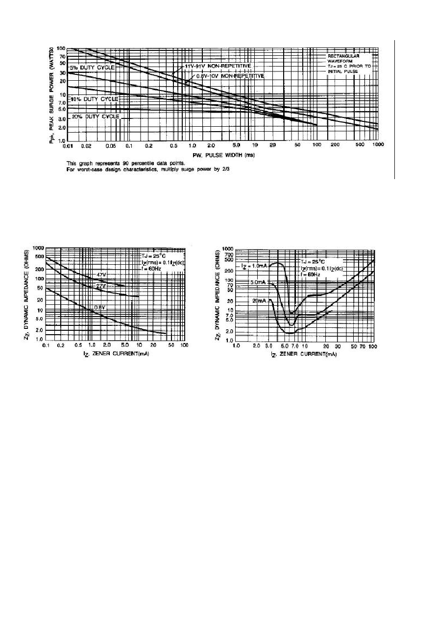
is as described in Figure 5.

RATING AND CHARACTERISTICS CURVES
1N4741A THRU 1M200Z
Fig. 1-POWER TEMPERATURE DERATING CUVE
Fig. 2-TEMPERATURE COEFFICIENTS
(-55 to +150 temperature range; 90% of the units are in the ranges indicated.)
Fig. 3-TYPICAL THERMAL RESISTANCE Fig. 4-EFFECT OF ZENER CURRENT
versus LEAD LENGTH
RATING AND CHARACTERISTICS CURVES
1N4741A THRU 1M200Z
Fig. 5-MAXIMUM SURGE POWER
Fig. 6-EFFECT OF ZENER CURRENT Fig. 7-EFFECT OF ZENER VOLTAGE
ON ZENER IMPEDANCE ON ZENER IMPEDANCE

RATING AND CHARACTERISTICS CURVES
1N4741A THRU 1M200Z
Fig. 9-TYPICAL CAPACITANCE versus Vz
Fig. 10-TYPICAL FORWARD CHARACTERISTICS
Fig. 8-TYPICAL LEAKAGE CURRENT