CP300 THRU CP3010
SINGLE-PHASE SILICON BRIDGE-P.C. MTG 2A, HEAT-SINK MTG 3A
VOLTAGE - 50 to 1000 Volts CURRENT - 3.0 Amperes
FEATURES
l
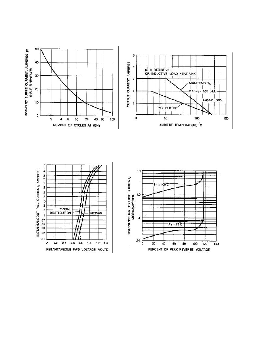
Surge overload rating--50 Amperes peak
l
Low forward voltage drop and reverse leakage
l
Small size, simple installation
l
Plastic package has Underwriter Laboratory
Flammability Classification 94V-O
l
Reliable low cost construction utilizing molded
plastic technique
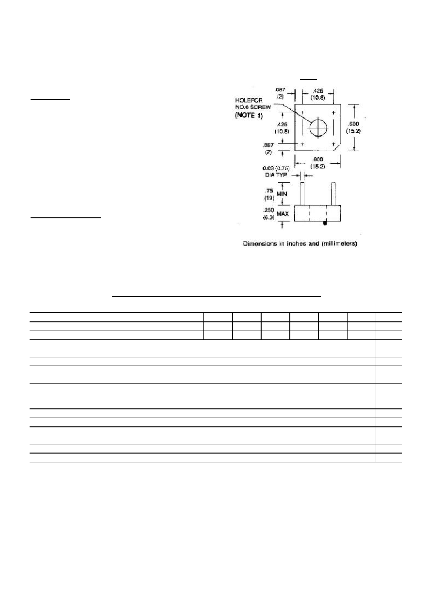
MECHANICAL DATA
Terminals: Leads solderable per MIL-STD-202,
Method 208
Weight: 0.08 ounce, 2.5 grams
MAXIMUM RATINGS AND ELECTRICAL CHARACTERISTICS
At 25 ambient temperature unless otherwise noted; resistive or inductive load at 60Hz.
CP300 CP301 CP302 CP304 CP306 CP308 CP3010
UNITS
Max Recurrent Peak Rev Voltage
50
100
200
400
600
800
1000
V
Max Bridge Input Voltage RMS
35
70
140
280
420
560
700
V
Max Average Rectified Output at T
C
=50 *
See Fig.2 at T
A
=25 **
3.0
2.0
A
Peak One Cycle Surge Overload Current
50
A
Max Forward Voltage Drop per element at
1.5A DC & 25 . See Fig.3
1.0
V
Max Rev Leakage at Rated DC Blocking
Voltage per element at 25
See Fig.4 at 100
10.0
1.0
A
m
A
I
2
t Rating for fusing ( t<8.3ms)
15.0
A
2
Sec
Typical Junction capacitance per leg(Note 4)CJ
21.0
P
F
Typical Thermal Resistance per leg(Note 2) R JA
(Note 3) R JL
12.0
8.0
/W
Operating Temperature Range
-55 TO +125
Storage Temperature Range
-55 TO +150
NOTES:
1. Bolt down on heat-sink with silicon thermal compound between bridge and mounting surface for
maximum heat transfer with #6 screw.
2. Unit mounted on 4.0
◊
4.0
◊
0.11" thick (10.5
◊
10.5
◊
0.3cm) AL. Plate.
3. Unit mounted on P.C.B at 0.375"(9.5mm) lead length with 0.5
◊
0.5" (12
◊
12mm) copper pads.
4. Measured at 1 MHz and applied reverse voltage of 4.0 Volts.
CP-3