ER1000F THRU ER1004F
ISOLATION SUPERFAST RECOVERY RECTIFIERS
VOLTAGE - 50 to 400 Volts CURRENT - 10.0 Amperes
FEATURES
l
Plastic package has Underwriters Laboratory
Flammability Classification 94V-O utilizing
Flame Retardant Epoxy Molding Compound
l
Exceeds environmental standards of MIL-S-19500/228
l
Low power loss, high efficiency
l
Low forward voltage, high current capability
l
High surge capacity
l
Super fast recovery times, high voltage
l
Epitaxial chip construction
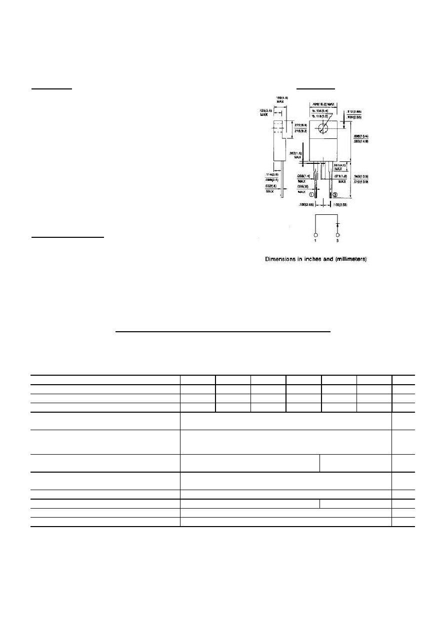
MECHANICAL DATA
Case: ITO-220AC full molded plastic package
Terminals: Leads, solderable per MIL-STD-202, Method 208
Polarity: As marked
Mounting Position: Any
Weight: 0.08 ounces, 2.24 grams
MAXIMUM RATINGS AND ELECTRICAL CHARACTERISTICS
Ratings at 25 ambient temperature unless otherwise specified.
Single phase, half wave, 60Hz, Resistive or inductive load.
For capacitive load, derate current by 20%.
ER1000F
ER1001F ER1001AF ER1002F
ER1003F
ER1004F UNITS
Maximum Recurrent Peak Reverse Voltage
50
100
150
200
300
400
V
Maximum RMS Voltage
35
70
105
140
210
320
V
Maximum DC Blocking Voltage
50
100
150
200
300
400
V
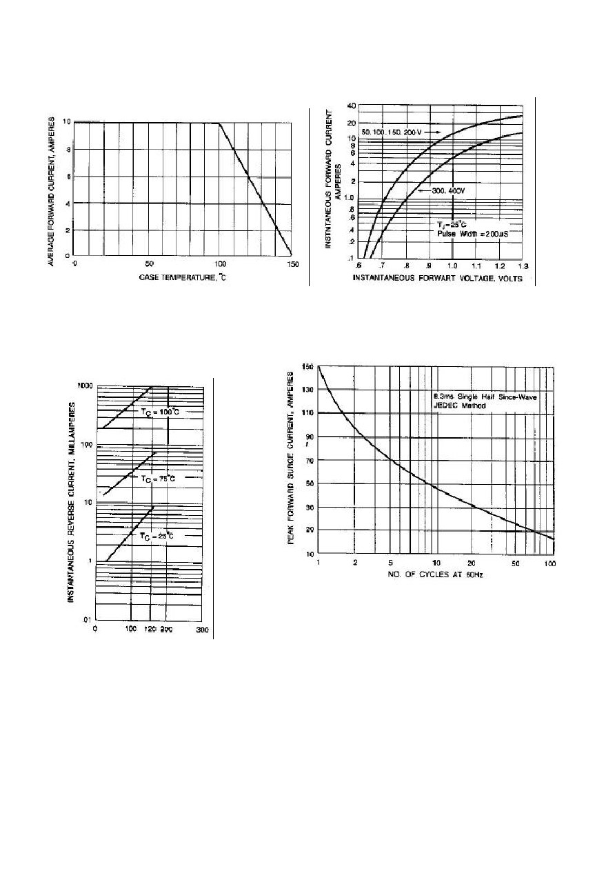
Maximum Average Forward Rectified
Current at T
C
=100
10.0
A
Peak Forward Surge Current,
8.3ms single half sine-wave superimposed
on rated load(JEDEC method)
150
A
Maximum Forward Voltage at 10.0A per
element
0.95
1.30
V
Maximum DC Reverse Current at Rated
T
a
=25
DC Blocking Voltage per element T
a
=125
10
500
A
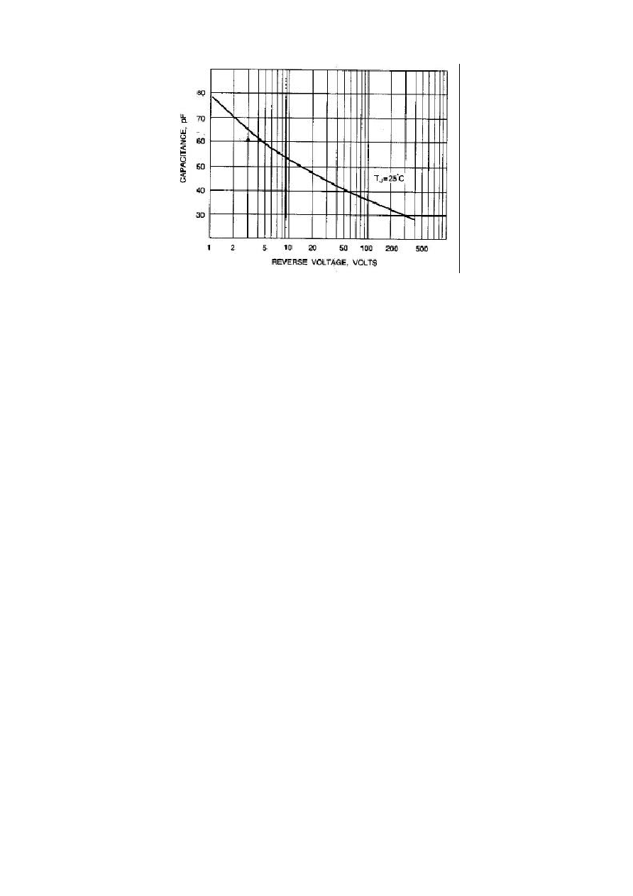
Typical Junction capacitance (Note 1)
62
P
F
Maximum Reverse Recovery Time(Note 2)
35
50
ns
Typical Thermal Resistance(Note 3) R JC
3.0
/W
Operating and Storage Temperature Range T
J
-55 to +150
NOTES:
1. Measured at 1 MHz and applied reverse voltage of 4.0 VDC
2. Reverse Recovery Test Conditions: I
F
=.5A, I
R
=1A, Irr=.25A
ITO-220AC