T-1 3/4 (
5mm)
InGaN LED LAMPs
MVL-584SG
Description
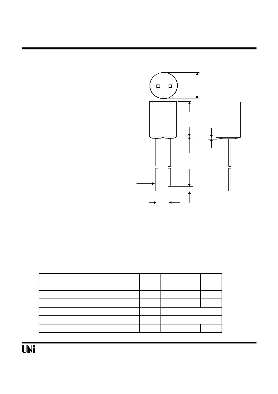
Package Dimensions
The MVL-584SG, a green source color device, is made with
InGaN on SiC substrate LED die.
The package is T-1 3/4 (
5
mm) water clear plastic type .
Applications
l
Full color displays & moving message signs
l
Solid state incandescent replacement bulbs
l
High ambient panel indicators
l
Color printers & scanners
l
Medical & Analytical instruments
Features
l
High performance - 2.0mW (505nm)
l
Superior SiC substrate technology
l
Excellent chip to chip consistency
l
High reliability
Absolute Maximum Ratings
Parameter
Symbol
Maximum Rating
Unit
Peak Forward Current(1/10 Duty Cycle@1KHz )
I
pf
100
mA
Continuous Forward Current
I
af
30
mA
Reverse Voltage
V
R
5
V
Operating Temperature Range
T
opr
-20
o
C
to +80
o
C
Storage Temperature Range
T
stg
-30
o
C
to +100
o
C
Electrostatic Discharge Threshold(HBM)
E
ot
1000
V
08/31/2000
Unity Opto Technology Co., Ltd.
@ T
A
=25
o
C
SEE NOTE 2
Unit : mm (inches)
Notes :
1. Tolerance is � 0.25 mm (.010") unless otherwise noted.
2. Protruded resin under flange is 1.5 mm (.059") max.
3. Lead spacing is measured where the leads emerge from the package.
2.54 nom.
(.100)
0.50 typ.
(.019)
5.00
(.197)
1.00 min
(.039)
ANODE
CATHODE
25.00 min
(0.984)
6.80
(.268)
SEE NOTE 3

MVL-584SG
Optical-Electrical Characteristics
Parameter
Test Conditions
Symbol
Min .
Typ .
Max .
Unit .
Luminous Intensity
I
F
=20mA
I
V
90
180
-
mcd
Forward Voltage
I
F
=20mA
V
F
-
3.5
4.0
V
Reverse Current
I
R
-
-
10
�
A
Dominant Wavelength
I
F
=20mA
d
-
505
-
nm
Viewing Angle
I
F
=20mA
2
1/2
-
75
-
deg.
Typical Optical-Electrical Characteristic Curves
08/31/2000
V
R
=5V
@
T
A
=25
o
C
Relative Luminous Intensity
Unity Opto Technology Co., Ltd.
0.1
1
10
0
25
50
75
Ambient Temperature (
o
C
)
FIG.5 LUMINOUS INTENSITY VS.
AMBIENT TEMPERATURE
Relative Luminous Intensity
0.5 0.3 0.1 0.2 0.4 0.6
FIG.6 RADIATION DIAGRAM
1.0
0.9
0.8
30
o
40
o
50
o
60
o
70
o
80
o
90
o
0
o
10
o
20
o
0
0.5
1
380
450
520
590
660
Wavelength (nm)
FIG.1 RELATIVE INTENSITY LUMINOUS
VS. WAVELENGTH
Relative Luminous
Intensity
0
5
10
15
20
25
30
0
1
2
3
4
Forward Voltage (V)
FIG.2 FORWARD CURRENT VS.
FORWARD VOLTAGE
Forward Current I
F
(mA)
0
10
20
30
40
0
25
50
75
100
Forward Current I
F
(mA)
Ambient Temperature (
o
C
)
FIG.3 FORWARD CURRENT VS.
AMBIENT TEMPERATURE
0.00
0.25
0.50
0.75
1.00
1.25
1.50
0
5
10 15 20 25 30
Forward Current I
F
(mA)
FIG.4 RELATIVE LUMINOUS INTENSITY
VS. FORWARD CURRENT
Relative Luminous Intensity
Normalized at I
F
=20mA