
GaAlAs HIGH POWER T0-46 PACKAGE
INFRARED EMITTING DIODE
MIE-404L3
Description
Package Dimensions
The MIE-404L3 is an infrared emitting diode with
GaAlAs / GaAlAs die technology molded in a water
clear plastic package.
Features
l
Standard TO-46 package
l
Peak wavelength
p
= 880 nm
l
Good spectral matching to si-photodetector
l
Radiant angle : 25∞
Absolute Maximum Ratings
@ T
A
=25
o
C
Parameter
Maximum Rating
Unit
Power Dissipation
120
mW
Peak Forward Current(300pps,10
µ
s pulse)
1
A
Continuos Forward Current
100
mA
Reverse Voltage
5
V
Operating Temperature Range
-55
o
C to +100
o
C
Storage Temperature Range
-55
o
C to +100
o
C
Lead Soldering Temperature
260
o
C for 5 seconds
02/04/2002
Unity Opto Technology Co., Ltd.
Unit : mm (inches )
Notes :
1. Tolerance is ± .010" unless otherwise noted.
2. Protruded resin under flange is .031"max.
3. Lead spacing is measured where the leads emerge from the package.
5.46
(.215)
.50 TYP.
(.020)
2.54
(.100)
.70
(.028)
5.60
(.221)
4.75
(.187)
1.00 MIN
(.040)
.25 MAX
(.059 )
CATHODE
INDICATOR
45∞
25.00 MIN
(.984)
A
C
MIE-404L3
Optical-Electrical Characteristics
@ T
A
=25
o
C
Parameter
Test Conditions
Symbol
Min.
Typ .
Max.
Unit
Radiant Intensity
I
F
=20mA
Ie
-
2.6
-
mW/sr
Forward Voltage
I
F
=50mA
V
F
-
1.4
1.70
V
Reverse Current
V
R
= 5V
I
R
-
-
100
µ
A
Peak Wavelength
I
F
=20mA
p
-
880
-
nm
Spectral Bandwidth
I
F
=20mA
-
80
-
nm
View Angle
I
F
=20mA
2
1/2
-
25
-
deg.
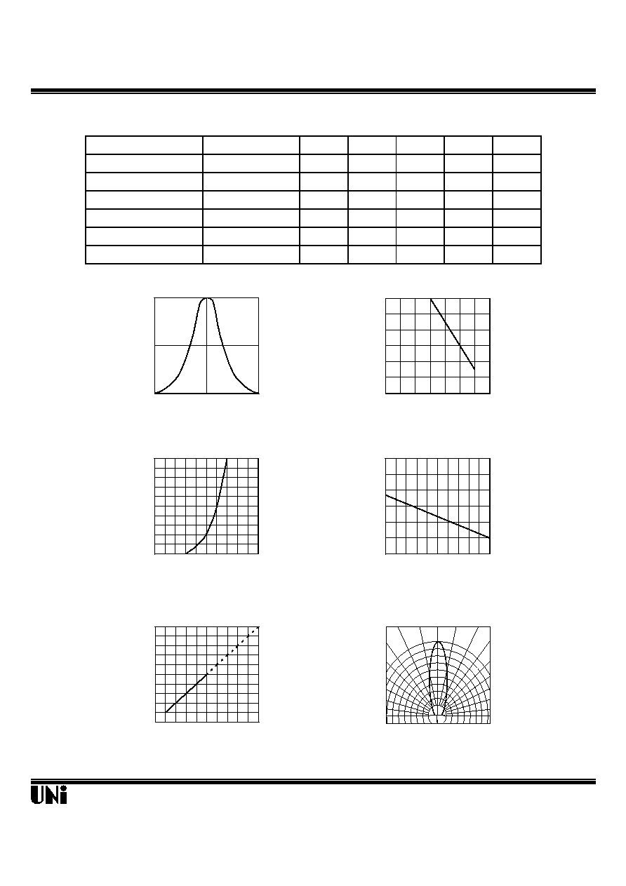
Typical Optical-Electrical Characteristic Curves
02/04/2002
Unity Opto Technology Co., Ltd.
0
50
60
70
80
90
100
0
1
2
3
4
5
0
20
40
60
80
100
Relative Radiant Intensity
Forward Current (mA)
FIG.5 RELATIVE RADIANT INTENSITY
VS. FORWARD CURRENT
0
20
40
60
80
100
0.8
1.0
1.2
1.4
1.6
1.8
Forward Voltage (V)
FIG.3 FORWARD CURRENT VS.
FORWARD VOLTAGE
Forward Current (mA)
0.0
0.5
1.0
1.5
2.0
2.5
3.0
-40 -20
0
20
40
60
Relative Radiant Intensity
Ambient Temperature T
A
(
o
C)
FIG.4 RELATIVE RADIANT INTENSITY
VS. AMBIENT TEMPERATURE
0
0.5
1
800
880
960
Relative Radiant Intensity
Wavelength (nm)
FIG.1 SPECTRAL DISTRIBUTION
Ambient Temperature T
A
(
o
C)
FIG.2 FORWARD CURRENT VS.
AMBIENT TEMPERATURE
-55
0
50
100
Forward Current I
F
(mA)
FIG.6 RADIATION DIAGRAM
0.5
0.3
0.1
0.2
0.4
0.6
30∞
40∞
90∞
70∞
60∞
50∞
80∞
1.0
0.9
0.8
Relative Radiant Intensity
0∞ 10∞ 20∞