Fiber Optic Receiver
MOF-R3K3
Features
1.Uni-directional data transmission using plastic fiber
2.Signal transmission speed
:MAX. 6 Mbps (NRZ signal)
3.Operating voltage :4.75 to 5.25 V
4.TTL compatible
5.Suitable for MOF-T3K3 Transmitter
NOTES:
Absolute Maximum Ratings
Symbol
Rating
Unit
Supply voltage
V
cc
-0.5 to + 7
V
High Level Output Current
I
OH
-1
mA
Low Level Output Current
I
OL
5
mA
Operating temperature
T
opr
-20 to +70
o
C
Storage temperature
T
stg
-30 to +80
o
C
Soldering Temperature
T
SOL
260*
o
C
* For 5s (1 times or less)
REV: A2
09/11/2001
Parameter
Unity Opto Technology Co., Ltd.
@ T
A
=25
o
C
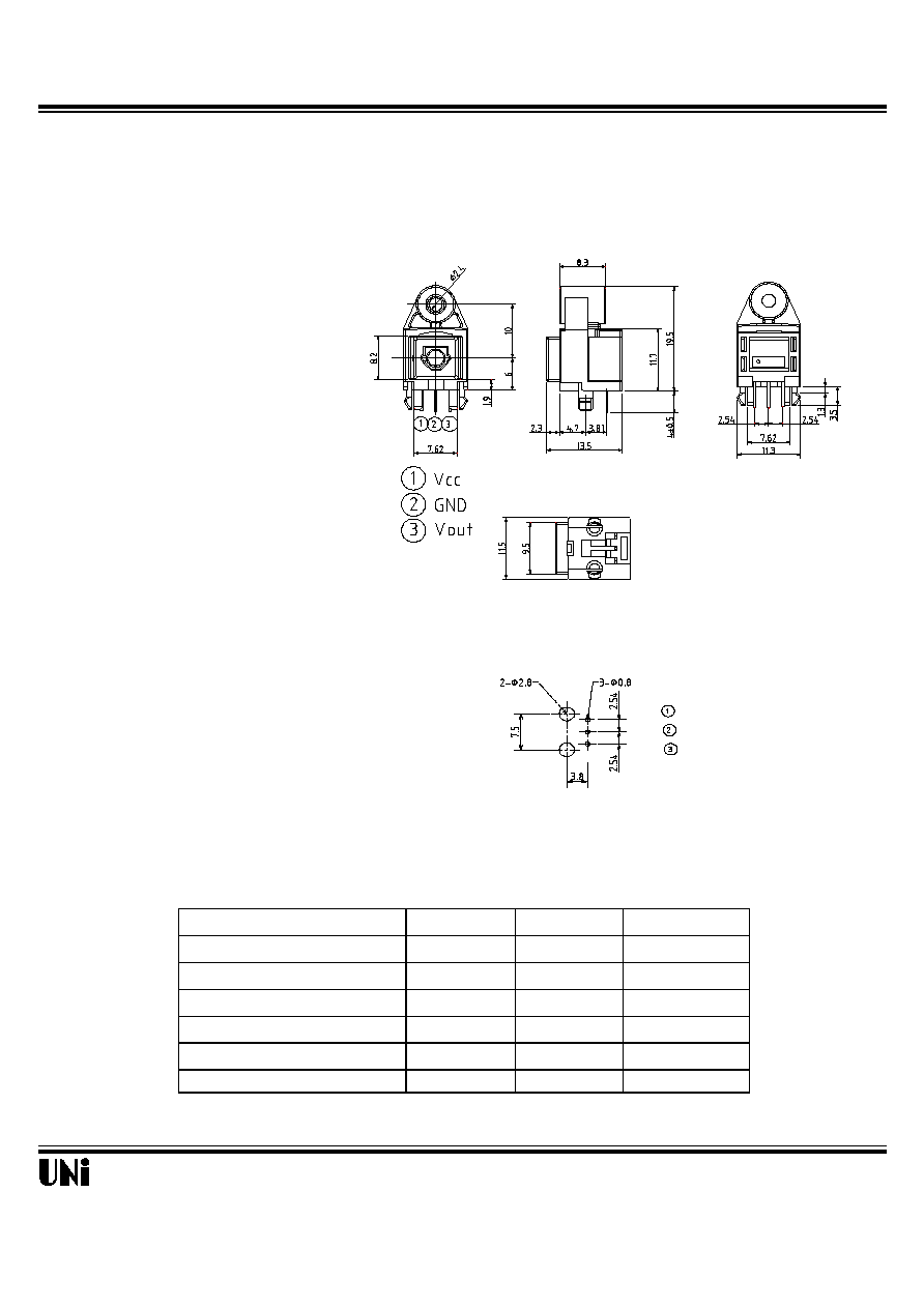
Tolerance is �0.3mm unless otherwise noted.
Recommended drilling as viewd from the soldering face
Outline Dimensions
Vcc
GND
Vout
1/4
Fiber Optic Receiver
MOF-R3K3
Recommended Operating Conditions
Operating supply voltage
Operating transfer rate
receiver input optical power level
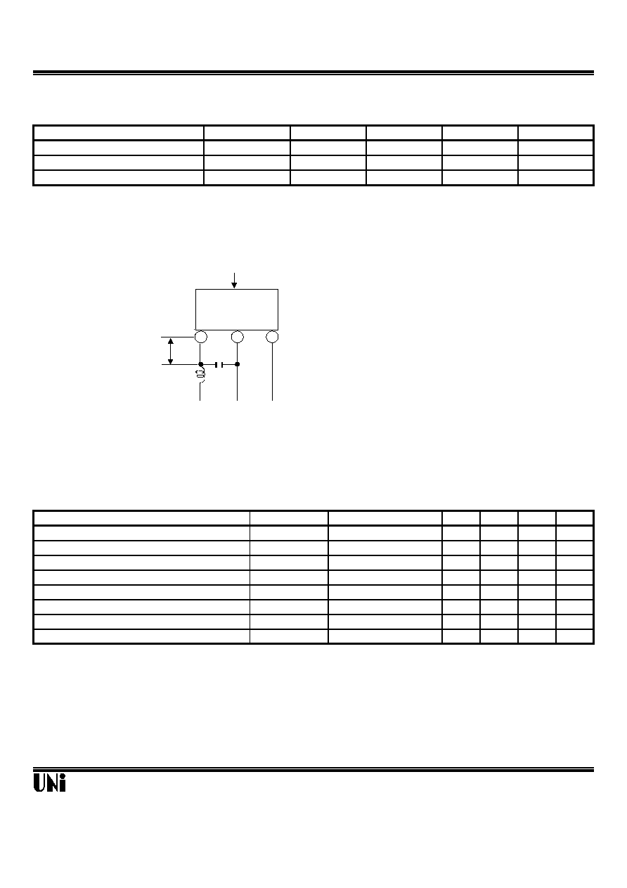
Recommended Connection Method
Electro-Optical Characteristics
MIN. TYP. MAX. Unit
---
20
40
mA
2.7
4.4
---
V
---
0.2
0.4
V
Rise time
---
20
40
ns
Fall time
---
20
40
ns
---
---
180
ns
---
---
180
ns
-30
---
+30
ns
REV: A2
Refer to Fig. 2
Refer to Fig. 2
Refer to Fig. 2
Refer to Fig. 2
Refer to Fig. 2
Refer to Fig. 2
Refer to Fig. 2
Pulse width distortion
t
pLH
t
pHL
tw
Low High delay time
High Low delay time
High level output voltage
Low level output voltage
t
r
t
f
V
OH
V
OL
Parameter
6
Dissipation current
Refer to Fig. 1
I
cc
Pc
Conditions
Symbol
Mbps
Parameter
MIN.
TYP.
MAX.
Symbol
V
cc
T
0.1
---
09/11/2001
Unit
4.75
5.0
5.25
dBm
-14.5
---
-22
V
Unity Opto Technology Co., Ltd.
Fiber Optic
Receiving
Module
Fiber Optic Connector
insert
2
3
1
Vcc
GND
Vout
Less than 7mm
0.1
�
F
47�
H
(Bottom view)
2/4
Fiber Optic Receiver
MOF-R3K3
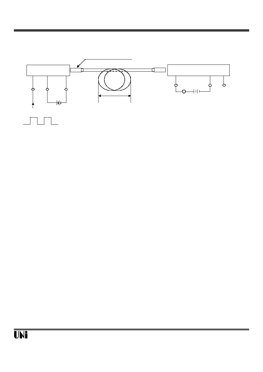
Fig. 1 Measuring Method of Optical Output Coupling with Fiber
Notes (1)Vcc=5.0V (State of operating)
(2)To bundle up the standard fiber optic cable, make it into a loop with the diameter D=10cm or more.
(3)P
c
= -14.5 dBm
(4)Measured on an ammeter.
REV: A2
09/11/2001
Fiber optic cable
V
OUT
V
CC
A
MOF-R3K3
Standard transmitter
MOF-T3K3
V
CC
5V
GND
V
in
Ammeter V
CC
Input
GND
D
6 Mbps NRZ, Duty 50% or 3 Mbps biphase mark PRBS signal
Unity Opto Technology Co., Ltd.
3/4

Fiber Optic Receiver
MOF-R3K3
Fig. 2 Measuring Method of Output Voltage and Pulse Response
Fiber optic cable
Test item
Symbol
Low High pulse delay time
t
PLH
High Low pulse delay time
t
PHL
Rise time
t
r
Fall time
t
f
tw
High level output voltage
V
OH
Low level output voltage
V
OL
REV: A2
Test item
Pulse width distortion
tw = t
PHL
- t
PLH
09/11/2001
Unity Opto Technology Co., Ltd.
Standard transmitter
MOF-T3K3
V
in
GND
V
CC
5V
MOF-R3K3
CH2
CH1
Oscilloscope
Input
6 Mbps NRZ, Duty 50%
V
CC
GND
V
OUT
t
r
t
PLH
90%
V
OL
V
OH
50%
50%
10%
t
f
t
PHL
Standard transmitter
Input signal
(CH1)
Output signal
(CH2)
V
CC
4/4