 | –≠–ª–µ–∫—Ç—Ä–æ–Ω–Ω—ã–π –∫–æ–º–ø–æ–Ω–µ–Ω—Ç: MOF-T3C6 | –°–∫–∞—á–∞—Ç—å:  PDF PDF  ZIP ZIP |
Fiber Optic Transmitter
MOF-T3C6
Features
1.Uni-directional data transmission
using plastic fiber
2.Signal transmission speed
:MAX. 13.2Mbps (NRZ signal)
3.Operating voltage :2.75 to 5.25 V
4.TTL and high speed C-MOS LOGIC
IC compatible
NOTES:
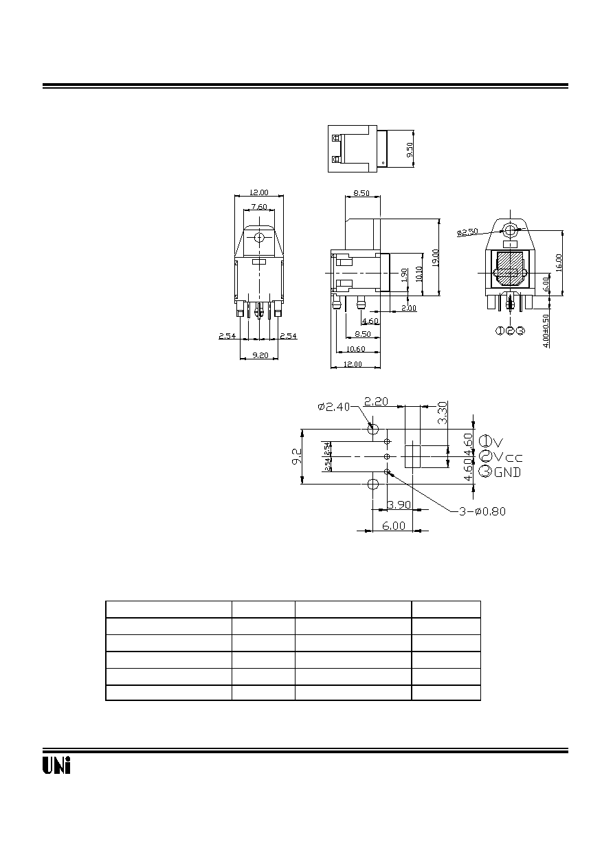
Tolerance is ±0.3mm unless otherwise noted.
@TA=25
o
C
Symbol
Rating
Unit
V
cc
-0.5 to + 7.0
V
V
in
-0.5 to Vcc +0.5
V
T
opr
-20 to +70
o
C
T
stg
-30 to +80
o
C
T
sol
260
o
C
*1 For 5s (2 times or less)
REV: A3
04/25/2002
Absolute Maximum Ratings
Storage temperature
Parameter
Soldering temperature
*1
Supply voltage
Input voltage
Operating temperature
Unity Opto Technology Co., Ltd.
Recommended drilling as viewd from the soldering face
Outline Dimensions
!"
1/4
Fiber Optic Transmitter
MOF-T3C6
Recommended Operating Conditions
Parameter
Symbol
MIN.
TYP.
MAX.
Unit
Operating supply voltage
V
cc
2.75
---
5.25
V
Operating transfer rate
T
---
---
13.2
Mbps
Electro-Optical Characteristics
Parameter
Symbol
Conditions
MIN.
TYP.
MAX.
Unit
Peak emission wavelength
p
630
660
690
nm
Optical power output coupling with fiber
P
c
Refer to Fig. 1
-21
-18
-15
dBm
Dissipation current
I
cc
Refer to Fig. 2
---
8
13
mA
High level input voltage
V
iH
Refer to Fig. 2
2.1
---
V
cc
V
Low level input voltage
V
iL
Refer to Fig. 2
---
---
0.8
V
Low High delay time
t
pLH
Refer to Fig. 3
---
100
180
ns
High Low delay time
t
pHL
Refer to Fig. 3
---
100
180
ns
Pulse width distortion
tw
Refer to Fig. 3
-15
---
+15
ns
REV : A3
04/25/2002
Unity Opto Technology Co., Ltd.
2/4
Fiber Optic Transmitter
MOF-T3C6
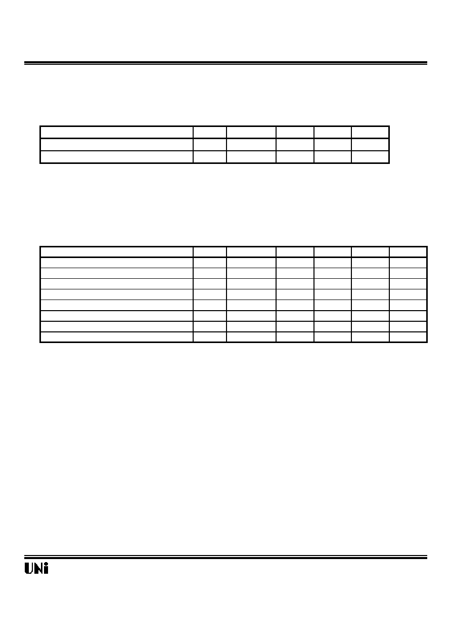
Fig. 1 Measuring Method of Optical Output Coupling with Fiber
Standard optical fiber cable
Fig. 2 Measuring Method of Intput Voltage and Supply Current
Standard optical fiber cable
Input conditions and judgement method
Judgement method
Note: V
cc
=5.0V (State of operating)
REV : A3
04/25/2002
Conditions
V
in
=2.1V or more
V
in
=0.8V or less
-21dBm<=Pc<=-15dBm, Icc=13mA or less
Pc<=-36dBm, Icc=13mA or less
Unity Opto Technology Co., Ltd.
Notes (1)Vcc=5.0V (State of operating)
(2)To bundle up the standard fiber optic cable, make it into a loop with the diameter D=10cm or more.
Optical power meter
MOF-T3C6
Unit to be measured
D
The optical power meter must be calibrated
to have the wavelength sensitivity of 660 nm.
( 0dBm=1mW )
V
CC
V
CC
GND
V
in
MOF-T3C6
Unit to be measured
The optical power meter must be calibrated
to have the wavelength sensitivity of 660 nm.
( 0dBm=1mW )
V
in
I
cc
V
in
GND
V
CC
V
CC
3/4
Fiber Optic Transmitter
MOF-T3C6
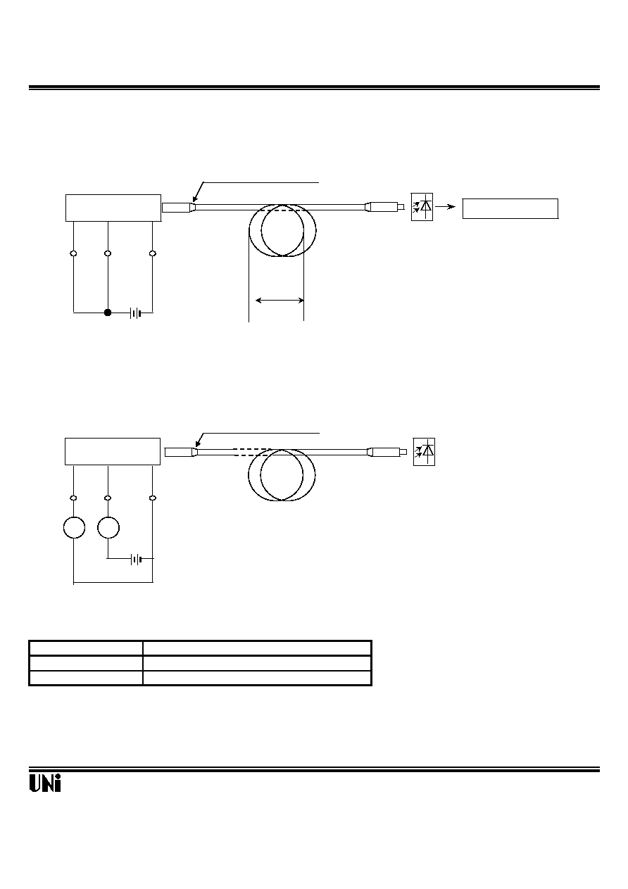
Fig.3 Measuring Method of Pulse Response
Standard optical fiber cable
t
PLH
t
PHL
Test item
Test item
Symbol
Low High pulse delay time
t
PLH
Refer to the above prescriptions
High Low pulse delay time
t
PHL
Refer to the above prescriptions
Pulse width distortion
tw
tw=t
PHL
- t
PLH
Notes
(1) The waveform write time shall be 4 seconds. But do not allow the waveform to be distorted by increasing the brightness too much.
(2 ) Vcc=5.0 V (State of operating)
(3) The probe for the oscilloscope must be more than 1M and less than 10pF.
REV : A3
04/25/2002
Test condition
Unity Opto Technology Co., Ltd.
Standard receiver
MOF-T3C6
Unit to be measured
V
CC
GND
V
in
6.6Mbps biphase
PRBS signal
Standard receiver output
Input signal
CH2
CH1
Oscilloscope
Output signal
V
CC
Input
1
1
0
0
50%
50%
4/4