
T-1 3/4 PACKAGE
SOLID STATE LAMP
MVL-534UG
Description
Package Dimensions
The MVL-534UG, a Green source color device, is made with
Gallium Phosphide on Gallium Phosphide light emitting diode.
The package is T-1 3/4(5mm) standard green transparent plastic
lens package.
Features
l
Standard T-1 3/4 (
5
mm) Package
l
High Intensity
l
General Purpose Leads
l
Wide Viewing Angle
Absolute Maximum Ratings
@ T
A
=25
o
C
Parameter
Symbol
Maximum Rating
Unit
Power Dissipation
P
ad
100
mW
Peak Forward Current(1/10 Duty Cycle.1ms pulse )
I
pf
120
mA
Continuous Forward Current
I
af
50
mA
Derating Linear From 25
0.4
mA/
o
C
Reverse Voltage
V
R
4
V
Operating Temperature Range
T
opr
-55
o
C
to +100
o
C
Storage Temperature Range
T
stg
-55
o
C
to +100
o
C
Solder temperature 1.6 mm from body for 5 seconds at 260
o
C
09/05/2000
Notes :
1. Tolerance is �0.25 mm (.010") unless otherwise noted.
2. Protruded resin under flange is 0.8 mm (.031") max.
3. Lead spacing is measured where the leads emerge from the package.
Unity Opto Technology Co., Ltd.
SEE NOTE 2
7.62
(.300)
5.05
(.200)
1.00
(.040)
5.90
(.230)
2.54TYP.
(.100)
0.5 TYP.
(.020)
25.4 MIN.
(1.000)
1.00MIN.
(.040)
5.47
(.215)
SEE NOTE 3
A
C
Unit: mm ( inches )
MVL-534UG
Optical-Electrical Characteristics
@ T
A
=25
o
C
Parameter
Test Conditions
Symbol
Min .
Typ .
Max .
Unit .
Luminous Intensity
I
F
=20mA
I
V
500
1000
-
mcd
Forward Voltage
I
F
=20mA
V
F
-
2.1
2.8
V
Reverse Current
I
R
-
-
100
�
A
Peak Emission Wavelength
I
F
=20mA
p
-
575
-
nm
Spectral Line Half Width
I
F
=20mA
-
30
-
nm
Viewing Angle
I
F
=20mA
2
1/2
-
20
-
deg.
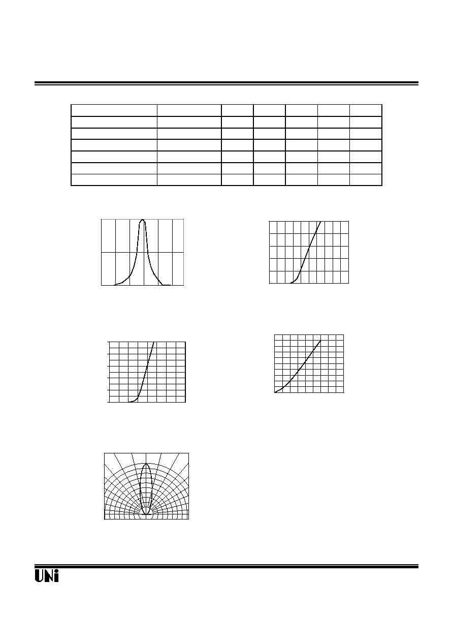
Typical Optical-Electrical Characteristic Curves
V
R
=5V
09/05/2000
Relative Luminous Intensity
Unity Opto Technology Co., Ltd.
0
1
2
3
4
5
0
10
20
30
40
Relative Luminous Intensity
Forward Current I
F
(mA)
FIG.4 RELATIVE LUMINOUS INTENSITY
VS. FORWARD CURRENT
0.5 0.3 0.1 0.2 0.4 0.6
FIG.5 RADIATION DIAGRAM
1.0
0.9
0.8
30
o
40
o
50
o
60
o
70
o
80
o
90
o
0
o
10
o
20
o
0
10
20
30
40
50
1.2
1.6
2
2.4
2.8
3.2
Forward Voltage (V)
FIG.2 FORWARD CURRENT VS.
FORWARD VOLTAGE
Forward Current I
F
(mA)
0
0.5
1
505
535
565
595
625
Wavelength (nm)
FIG.1 RELATIVE INTENSITY LUMINOUS
VS. WAVELENGTH
Relative Luminous Intensity
0
10
20
30
40
50
1.2
1.6
2
2.4
2.8
Forward Current
(mA)
Forward Voltage (V)
FIG.3 FORWARD CURRENT VS.
FORWARD VOLTAGE