T-1 3/4 PACKAGE
SOLID STATE LAMP
MVL-564BV
Description
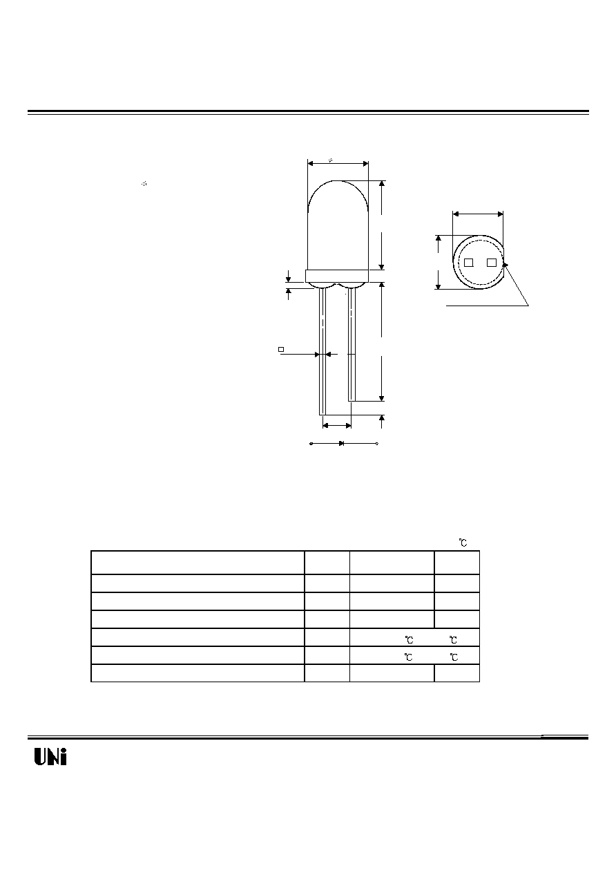
Package Dimensions
The MVL-564BV, a blue source color device, is made with
GaN ( on SiC substrate) LED die.
The package is T-1 3/4( 5mm) water clear plastic
lens package.
Applications
l
Full color displays & moving message signs
l
Solid state incandescent replacement bulbs
l
High ambient panel indicators
l
Color printers & scanners
l
Medical & Analytical instruments
Features
l
High performance - 1.15mW (430nm)
l
Superior SiC substrate technology
l
Excellent chip to chip consistency
l
High reliability
Absolute Maximum Ratings
Parameter
Symbol
Maximum Rating
Unit
Peak Forward Current(1/10 Duty Cycle@1KHz )
I
pf
70
mA
Continuous Forward Current
I
af
30
mA
Reverse Voltage
V
R
5
V
Operating Temperature Range
T
opr
-20 to +80
Storage Temperature Range
T
stg
-30 to +100
Electrostatic Discharge Threshold
E
ot
1000
V
08/24/2000
Notes :
1. Tolerance is �0.25 mm (.010") unless otherwise noted.
2. Protruded resin under flange is 0.8 mm (.031") max.
3. Lead spacing is measured where the leads emerge from the package.
Unity Opto Technology Co., Ltd.
@ T
A
=25
Unit: mm ( inches )
A
C
7.70
(.300)
5.00
(.200)
1.00
(.040)
2.54
(.100)
0.50 TYP.
(.020)
25.40 MIN
(1.000)
1.00MIN.
(.040)
5.90
(.230)
5.50
(.217)
FLAT DENOTES CATHODE
SEE NOTE 2
MVL-564BV
Optical-Electrical Characteristics
Parameter
Test Conditions
Symbol
Min .
Typ .
Max .
Unit .
Luminous Intensity
I
F
=20mA
I
V
60
150
-
mcd
Forward Voltage
I
F
=20mA
V
F
-
3.9
4.5
V
Reverse Current
I
R
-
-
10
�
A
Dominant Wavelength
I
F
=20mA
d
-
430
-
nm
Viewing Angle
I
F
=20mA
2
1/2
-
30
-
deg.
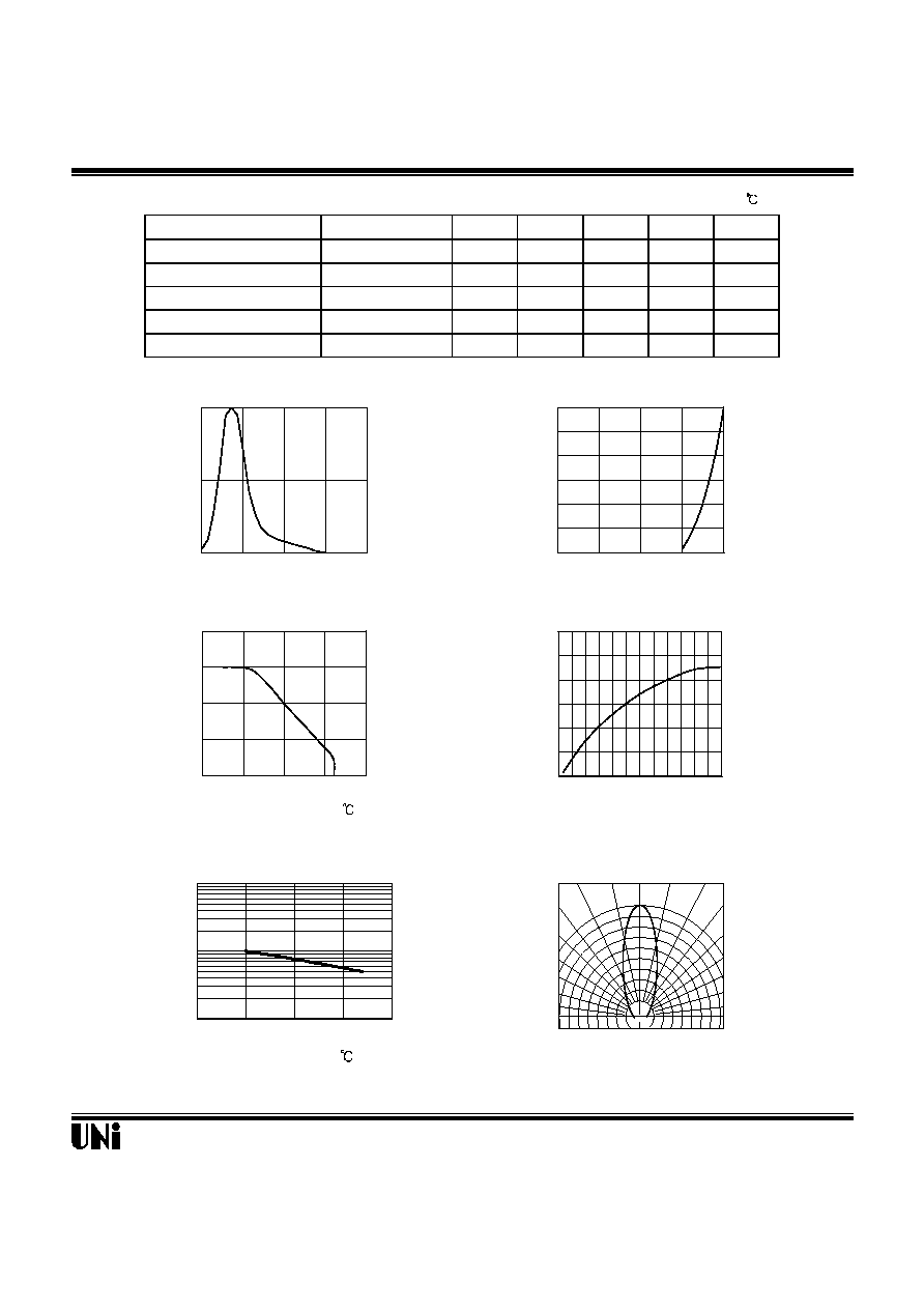
Typical Optical-Electrical Characteristic Curves
V
R
=5V
08/24/2000
@
T
A
=25
Unity Opto Technology Co., Ltd.
Relative Luminous Intensity
0.5 0.3 0.1 0.2 0.4 0.6
FIG.6 RADIATION DIAGRAM
1.0
0.9
0.8
30
o
40
o
50
o
60
o
70
o
80
o
90
o
0
o
10
o
20
o
0
0.5
1
380
450
520
590
660
Wavelength (nm)
FIG.1 RELATIVE INTENSITY LUMINOUS
VS. WAVELENGTH
Relative Luminous Intensity
0
5
10
15
20
25
30
0
1
2
3
4
Forward Voltage (V)
FIG.2 FORWARD CURRENT VS.
FORWARD VOLTAGE
Forward Current I
F
(mA)
0
10
20
30
40
0
25
50
75
100
Forward Current I
F
(mA)
Ambient Temperature ( )
FIG.3 FORWARD CURRENT VS.
AMBIENT TEMPERATURE
0.00
0.25
0.50
0.75
1.00
1.25
1.50
0
5
10
15
20
25
30
Forward Current I
F
(mA)
FIG.4 RELATIVE LUMINOUS INTENSITY
VS. FORWARD CURRENT
Relative Luminous Intensity
Normalized at I
F
=20mA
0.1
1
10
0
25
50
75
100
Ambient Temperature ( )
FIG.5 LUMINOUS INTENSITY VS.
AMBIENT TEMPERATURE
Relative Luminous Intensity