UTC 2SC1815
NPN EPITAXIAL SILICON TRANSISTOR
UTC
UNISONIC TECHNOLOGIES CO. LTD
1
QW-R201-006,A
AUDIO FREQUENCY AMPLIFIER
HIGH FREQUENCY OSC NPN
TRANSISTOR
FEATURES
*Collector-Emitter voltage:
BV
CEO
=50V
*Collector current up to 150mA
* High hFE linearity
*complimentary to 2SA1015
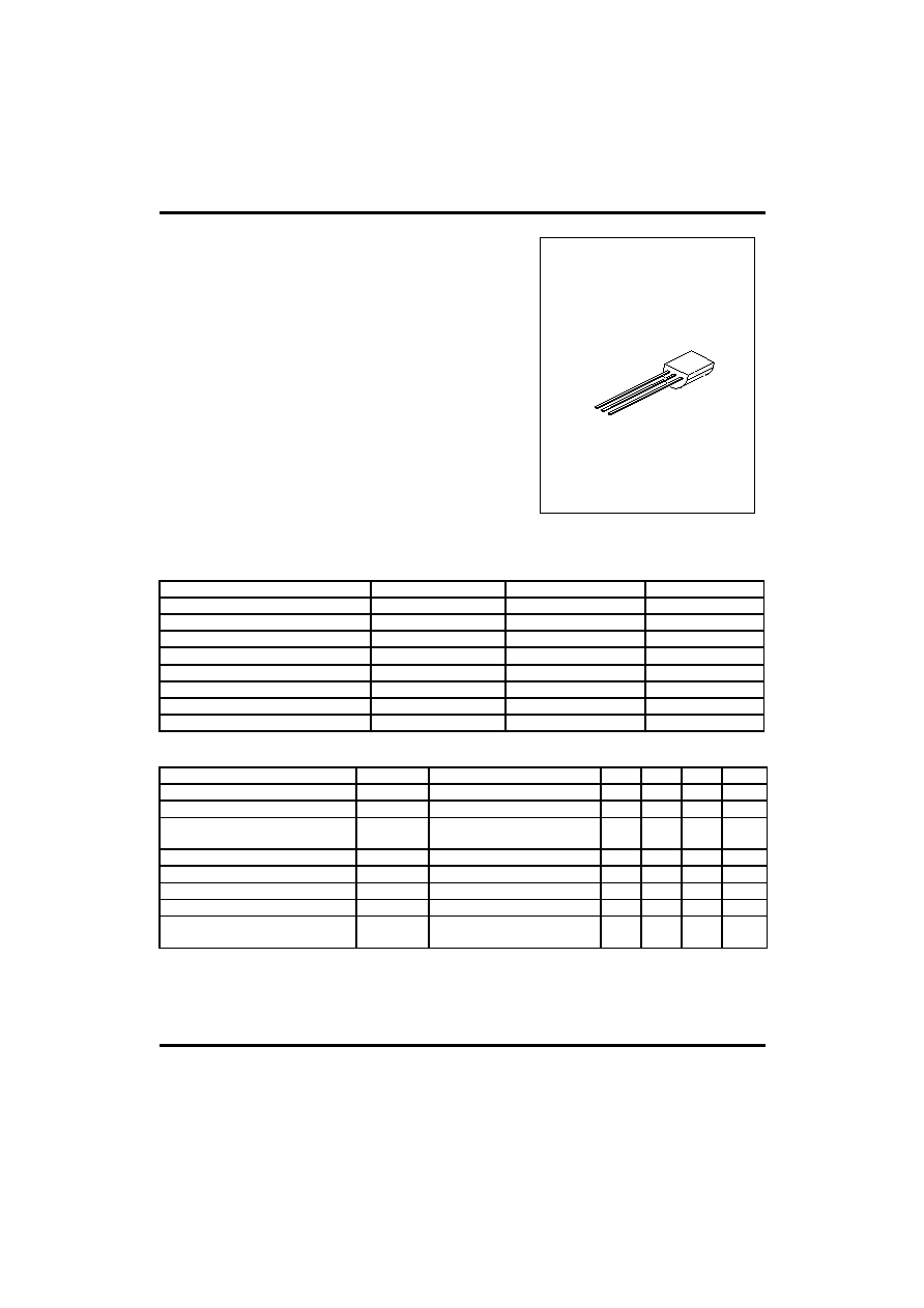
TO-92
1
1:EMITTER 2:COLLECTOR 3. BASE
ABSOLUTE MAXIMUM RATINGS
( Ta=25
∞C ,unless otherwise specified )
PARAMETER SYMBOL
RATING
UNIT
Collector-base voltage
V
CBO
60 V
Collector-emitter voltage
V
CEO
50 V
Emitter-base voltage
V
EBO
5 V
Collector dissipation(Ta=25
∞C
)
Pc 400
mW
Collector current
Ic
150
mA
Base current
I
B
50
mA
Junction Temperature
T
j
125
∞C
Storage Temperature
T
STG
-55 ~ +150
∞C
ELECTRICAL CHARACTERISTICS
(Ta=25
∞C,unless otherwise specified)
Parameter
Symbol
Test
conditions
MIN
TYP MAX UNIT
Collector cut-off current
I
CBO
V
CB
=60V,I
E
=0
100
nA
Emitter cut-off current
I
EBO
V
EB
=5V,Ic=0
100
nA
DC current gain(note)
h
FE1
h
FE2
V
CE
=6V,Ic=2mA
V
CE
=6V,Ic=150mA
70
25
700
Collector-emitter saturation voltage
V
CE
(sat) Ic=100mA,I
B
=10mA
0.1
0.25
V
Base-emitter saturation voltage
V
BE
(sat) Ic=100mA,I
B
=10mA
1.0
V
Current gain bandwidth product
f
T
V
CE
=10V,Ic=50mA 80
MHz
Output capacitance
Cob
V
CB
=10V,I
E
=0,f=1MHz
2.0
3.0
pF
Noise Figure
NF
Ic=-0.1mA,V
CE
=6V
R
G
=10k
,f=100Hz
1.0
1.0 dB

UTC 2SC1815
NPN EPITAXIAL SILICON TRANSISTOR
UTC
UNISONIC TECHNOLOGIES CO. LTD
2
QW-R201-006,A
CLASSIFICATION OF hFE1
RANK Y G L
RANGE 120-240 200-400 350-700
TYPICAL CHARACTERISTIC CURVES
Fig.1 Static characteristics
Collector-Emitter voltage ( V)
Ic,Co
l
l
e
cto
r
cu
r
r
e
n
t
(
m
A
)
0
4
8
12
16
20
0
20
40
60
80
100
Fig.2 DC current Gain
Ic,Collector current (mA)
H
FE
, DC cu
r
r
e
n
t
G
a
i
n
10
2
10
1
10
0
10
3
10
3
10
2
10
1
10
0
10
-1
V
CE
=6V
Fig.3 Base-Emitter on Voltage
10
-1
10
0
10
1
10
2
Ic,Co
l
l
e
cto
r
cu
r
r
e
n
t
(
m
A
)
Base-Emitter voltage (V)
0
0.2
0.4
0.6
0.8
1.0
V
CE
=6V
Ic,Collector current (mA)
10
3
10
2
10
1
10
0
10
-1
Sat
u
rat
i
on v
o
lt
age (m
V)
10
1
10
2
10
3
10
4
Fig.4 Saturation voltage
Fig.5 Current gain-bandwidth
product
Fig.6 Collector output
Capacitance
V
CE
(sat)
V
BE
(sat)
Ic=10*I
B
Ic,Collector current (mA)
10
0
10
1
10
2
10
3
C
u
rrent
Gain-bandw
idt
h
produc
t
,
f
T
(M
H
z
)
10
0
10
1
10
2
V
CE
=6V
Collector-Base voltage (V)
C
ob,
C
apac
it
anc
e (pF
)
10
0
10
1
10
2
10
0
10
1
10
2
10
3
f=1MHz
I
E
=0
I
B
=50
µA
I
B
=100
µA
I
B
=150
µA
I
B
=200
µA
I
B
=250
µA
I
B
=300
µA
10
-1
10
-1