TLWR992.
Document Number 83286
Rev. 1.2, 30-Nov-04
Vishay Semiconductors
www.vishay.com
1
19232
e3 Pb
Pb-free
TELUXTM
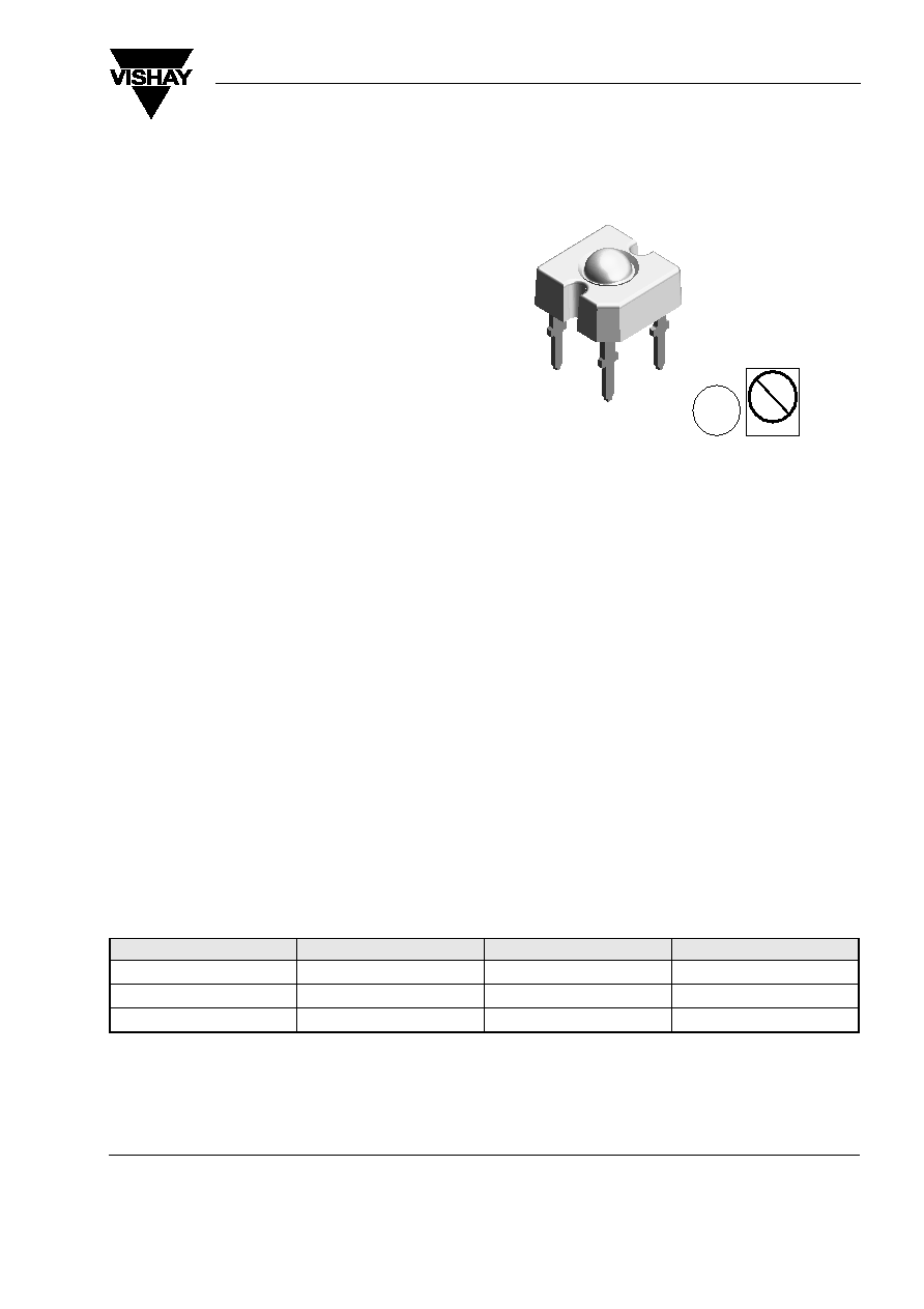
Description
The TELUXTM series is a clear, non diffused LED for
applications where supreme luminous flux is required.
It is designed in an industry standard 7.62 mm square
package utilizing highly developed with super bright,
AllnGaP, OMA technology.
The supreme heat dissipation of TELUXTM allows
applications at high ambient temperatures.
All packing units are binned for luminous flux, forward
voltage and color to achieve the most homogenous
light appearance in application.
SAE and ECE color requirements for automobile
application are available for color red.
ESD resistivity 2kV (HBM) according to MIL
STD 883D, method 3015.7.
Features
∑ Utilizing one of the world's brightest (AS) AllnGaP
technologies (OMA)
∑ High luminous flux
∑ Supreme heat dissipation: R
thJP
is 90 K/W
∑ High operating temperature:
T
amb
= - 40 to + 110 ∞C
∑ Meets SAE and ECE color requirements for the
automobile industry for color red
∑ Packed in tubes for automatic insertion
∑ Luminous flux, forward voltage and color catego-
rized for each tube
∑ Small mechanical tolerances allow precise usage
of external reflectors or lightguides
∑ Lead-free device
Applications
Exterior lighting
Tail-, Stop - and Turn Signals of motor vehicles
Replaces small incandescent lamps
Traffic signals and signs
Parts Table
Part
Color, Luminous Intensity
Angle of Half Intensity (±
)
Technology
TLWR9920
Red,
V
> 3000 mlm
45 ∞
AllnGaP on GaAs
TLWR9921
Red,
V
> 3500 mlm
45 ∞
AllnGaP on GaAs
TLWR9922
Red,
V
> 4000 mlm
45 ∞
AllnGaP on GaAs
www.vishay.com
2
Document Number 83286
Rev. 1.2, 30-Nov-04
VISHAY
TLWR992.
Vishay Semiconductors
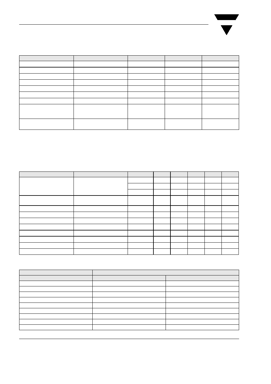
Absolute Maximum Ratings
T
amb
= 25 ∞C, unless otherwise specified
TLW.992.
Optical and Electrical Characteristics
T
amb
= 25 ∞C, unless otherwise specified
Red
TLW.992.
Forward Voltage Classification
Parameter
Test condition
Symbol
Value
Unit
Reverse voltage
I
R
= 100
µA
V
R
10
V
DC Forward current
T
amb
85 ∞C
I
F
70
mA
Surge forward current
t
p
10 µs
I
FSM
0.1
A
Power dissipation
T
amb
85 ∞C
P
V
190
mW
Junction temperature
T
j
125
∞C
Operating temperature range
T
amb
- 40 to + 110
∞C
Storage temperature range
T
stg
- 55 to + 110
∞C
Soldering temperature
t
5 s, 1.5 mm from body
preheat temperature
100 ∞C/ 30 sec.
T
sd
260
∞C
Thermal resistance junction/
ambient
with cathode heatsink
of 70 mm
2
R
thJA
200
K/W
Parameter
Test condition
Part
Symbol
Min
Typ.
Max
Unit
Total flux
I
F
= 70 mA, R
thJA
= 200 ∞K/W
TLWR9920
V
3000
3700
mlm
TLWR9921
V
3500
4200
mlm
TLWR9922
V
4000
5000
mlm
Luminous intensity/Total flux
I
F
= 70 mA, R
thJA
= 200 ∞K/W
I
V
/
V
0.7
mcd/
mlm
Dominant wavelength
I
F
= 70 mA, R
thJA
= 200 ∞K/W
d
611
615
634
nm
Peak wavelength
I
F
= 70 mA, R
thJA
= 200 ∞K/W
p
624
nm
Angle of half intensity
I
F
= 70 mA, R
thJA
= 200 ∞K/W
± 45
deg
Total included angle
90 % of Total Flux Captured
0.9V
100
deg
Forward voltage
I
F
= 70 mA, R
thJA
= 200 ∞K/W
V
F
1.83
2.5
3.03
V
Reverse voltage
I
R
= 100
µA
V
R
10
20
V
Temperature coefficient <
d
I
F
= 70 mA
TC
d
17
nm/K
Temperature coefficient V
F
I
F
= 70 mA, T > - 25 ∞C
TC
VF
- 2.9
mV/K
Group
Forward Voltage (V)
min
max
Y
1.83
2.07
Z
1.95
2.19
0
2.07
2.31
1
2.19
2.43
2
2.31
2.55
3
2.43
2.67
4
2.55
2.79
5
2.67
2.91
6
2.79
3.03
VISHAY
TLWR992.
Document Number 83286
Rev. 1.2, 30-Nov-04
Vishay Semiconductors
www.vishay.com
3
Color Classification
Luminous Flux Classification
Typical Characteristics (Tamb = 25
∞C unless otherwise specified)
Group
Dominant Wavelength (nm)
min
max
1
611
618
2
614
622
3
616
624
Group
Luminous Intensity (mlm)
min
max
F
3000
4200
G
3500
4800
H
4000
6100
I
5000
7300
K
6000
9700
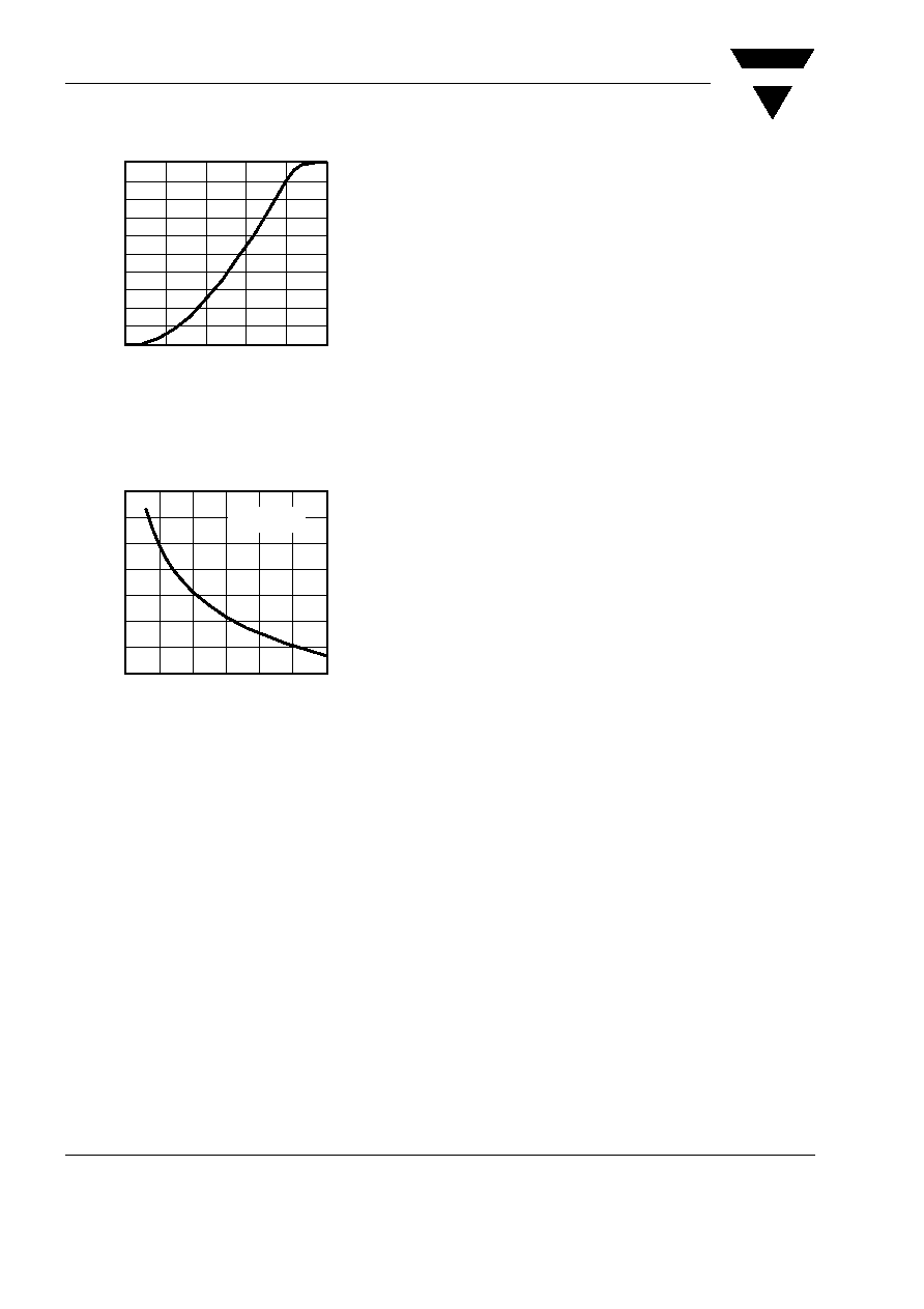
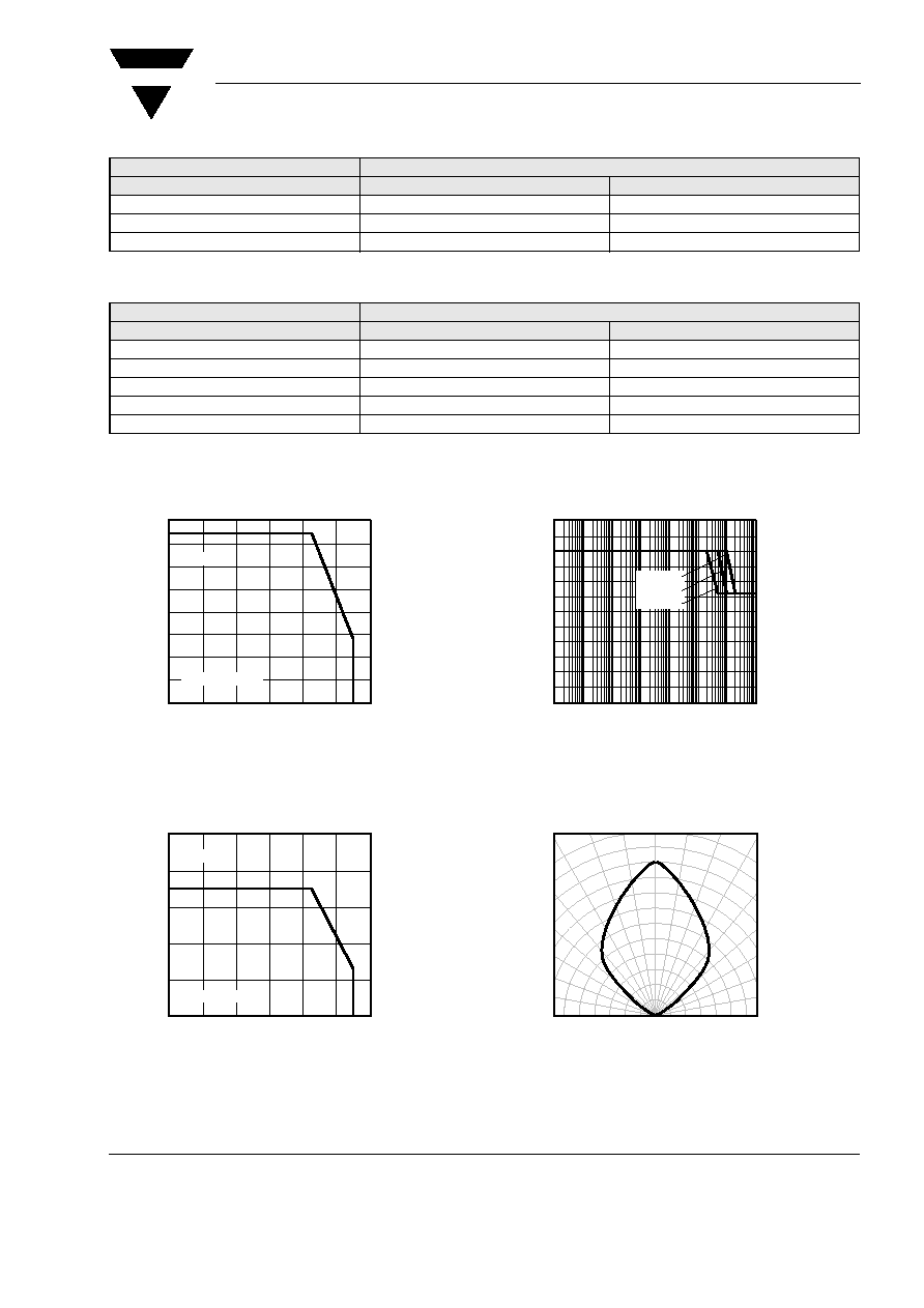
Figure 1. Power Dissipation vs. Ambient Temperature
Figure 2. Forward Current vs. Ambient Temperature
0
25
50
75
100
125
150
175
200
0
20
40
60
80
100
120
T
amb
≠ Ambient Temperature ( C )
15982
P
≠ Power Dissipation ( mW )
V
R
thJA
=200K/W
Red
0
20
40
60
80
100
0
20
40
60
80
100
120
T
amb
≠ Ambient Temperature ( C )
15983
I ≠ Forward Current ( mA
)
F
R
thJA
=200K/W
Red
Figure 3. Forward Current vs. Pulse Length
Figure 4. Rel. Luminous Intensity vs. Angular Displacement
0.00
0.02
0.04
0.06
0.08
0.10
0.12
t
p
≠ Pulse Length (ms)
I ≠Forward Current (A)
F
10
≠5
10
≠4
10
≠3
10
≠2
10
≠1
10
0
10
1
10
2
0.005
0.05
0.5
16731
16200
0.4
0.2
0
0.2
0.4
0.6
0.6
0.9
0
∞
30
∞
10
∞
20
∞
40
∞
50
∞
60
∞
70
∞
80
∞
1.0
0.8
0.7
Angular Displacement
I
-
Re
l
ati
v
e
L
uminous
Intensit
y
Vr
e
l