ZGL41-100 thru ZGL41-200A
Vishay Semiconductors
formerly General Semiconductor
Document Number 88409
www.vishay.com
02-May-02
1
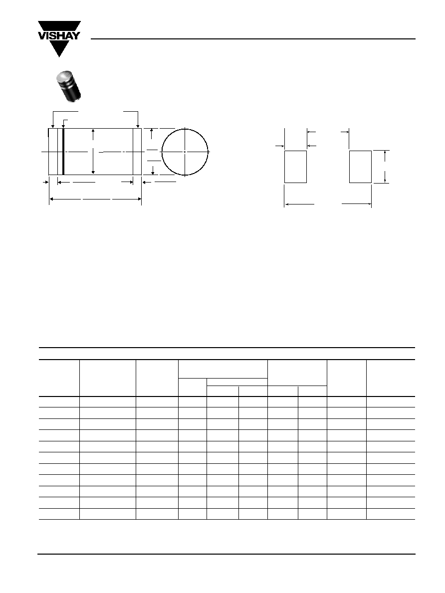
Surface Mount Glass Passivated Zeners
Zener Voltage 100 to 200V
Steady State Power 1.0W
Maximum Ratings and Electrical Characteristics
(T
A
= 25∞C unless otherwise noted)
Operating junction and storage temperature range: T
J
, T
STG
: -55∞C to +150∞C
Nominal Zener
Maximum Zener
Maximum DC Reverse
Maximum
Max. Instantaneous
Voltage at I
ZT
Dynamic Impedance
Leakage Current
Surge Current
Forward Voltage
(Note 1)
Test Current
Z
ZT
at
Z
ZK
at I
ZK
at V
R
(Note 2)
at 200mA
Type
V
Z
(V)
I
ZT
(mA)
I
ZT
(
)
(
)
(mA)
I
R
(
µ
A)
V
R
(V)
I
RM
(mAdc)
V
F
(V)
ZGL41-100
100
3.7
250
3100
0.25
1.0
76.0
10.0
1.5
ZGL41-110
110
3.4
300
4000
0.25
1.0
83.6
9.1
1.5
ZGL41-120
120
3.1
380
4500
0.25
1.0
91.2
8.3
1.5
ZGL41-130
130
2.9
450
5000
0.25
1.0
98.8
7.7
1.5
ZGL41-140
140
2.7
525
5500
0.25
1.0
106.4
7.1
1.5
ZGL41-150
150
2.5
600
6000
0.25
1.0
114.0
6.7
1.5
ZGL41-160
160
2.3
700
6500
0.25
1.0
121.6
6.3
1.5
ZGL41-170
170
2.2
800
6750
0.25
1.0
129.2
5.9
1.5
ZGL41-180
180
2.1
900
7000
0.25
1.0
136.9
5.6
1.5
ZGL41-190
190
2.0
1050
7500
0.25
1.0
144.4
5.3
1.5
ZGL41-200
200
1.9
1200
8000
0.25
1.0
152.0
5.0
1.5
Notes
:
(1) Standard voltage tolerance is ±10%, Suffix A = ±5%
(2) Surge current is a non-repetitive, 8.3ms pulse width square wave or equivalent sine-wave superimposed on I
ZT
per JEDEC Method
(3) Maximum steady state power dissipation is 1.0 watt at T
T
= 75
∞
C
Features
∑ Plastic package has Underwriters Laboratory Flammability
Classification 94V-0
∑ For surface mount applications
∑ Glass passivated junction
∑ Low Zener impedance
∑ Low regulation factor
∑ High temperature soldering guaranteed:
250∞C/10 seconds at terminals
Mechanical Data
Case: JEDEC DO-213AB molded plastic body over
passivated junction
Terminals: Solder plated, solderable per MIL-STD-750,
Method 2026
Polarity: Red band denotes Zener diode and
positive end (cathode)
Mounting Position: Any
Weight: 0.0046 oz., 0.116 g
Packaging codes/options:
26/5K per 13" Reel (12mm tape), 60K/box
46/1.5K per 7" Reel (12mm tape), 30K/box
Dimensions in inches
and (millimeters)
SOLDERABLE ENDS
1st BAND
0.022 (0.56)
0.018 (0.46)
0.205 (5.2)
0.185(4.7)
D1=
0.105
0.095
(2.67)
(2.41)
D2 = D1 + 0
- 0.008 (0.20)
1st band denotes type and positive end (cathode)
D2
0.022 (0.56)
0.018 (0.46)
DO-213AB
Mounting Pad Layout
0.157 (4.00)
0.118 (3.00) MIN
MAX
0.256 (6.50)
REF
0.049 (1.25) MIN

ZGL41-100 thru ZGL41-200A
Vishay Semiconductors
formerly General Semiconductor
www.vishay.com
Document Number 88409
2
02-May-02
Ratings and
Characteristic Curves
(T
A
= 25∞C unless otherwise noted)
0
0.25
0.5
0.75
1.0
75
25
50
100
125
150
175
P
M(A
V) -
-
A
verage Power Dissipation (W)
Terminals Temperature (
∞
C)
Fig. 1 -- Maximum Continuous Power
Dissipation
Z
Z
--
Dynamic Zener Impedance (
)
Fig. 2 -- Typical Zener Impedance
10
1
0.1
100
1,000
10,000
I
ZT
-- Zener Test Current (mA)
Fig. 5 -- Steady State Power
Derating Curve
180
160
140
120
100
80
200
220
100
130
110
140 150
160
170 180 190 200
V
Z
-
-
T
emperature Coef
ficient (mV/
∞
C)
Tested at Rated I
ZT
Instantaneous Forward Current (A)
0.01
0.1
1
10
0.4
0.6
0.8
Instantaneous Forward Voltage (V)
1
1.2
1.4
1.6
Pulse Width = 300
µ
s
1% Duty Cycle
T
J
= 25
∞
C
Fig. 3 -- Typical Instantaneous Forward
Characteristics
V
Z
-- Zener Voltage (V)
120
60Hz
Resistive or
Inductive Load
P.C.B. Mounted on
0.31 x 0.31 x 0.08 (8 x 8 x 2mm)
Copper Areas Pads
10
Instantaneous Reverse Current (
µ
A)
0.01
0.1
1
10
0
20
40
Percent of Rated Zener Voltage (%)
60
80
100
T
J
= 25
∞
C
T
J
= 100
∞
C
Fig. 4 -- Typical Reverse Characteristics
I
ZT
-
-
T
est Zener Current (mA)
0.1
1
10
100
150
200
V
Z
-- Zener Voltage (V)
250
Fig. 6 -- Typical Zener Voltage
V
Z
= 200V
V
Z
= 100V
V
Z
= 120V
V
Z
= 180V
V
Z
= 150V