75 South Street, Hopkinton, MA 01748 800-982-5737 508-435-6831 Fax: 508-435-5289 www.valpeyfisher.com
72
X O
VFAC3
Creating a Part Number
VFAC3
FREQUENCY STABILITY
Code
Specification
S
±
20 ppm
A
±
25 ppm
B
±
50 ppm
±
100
ppm (std.)
DUTY CYCLE
Code
Specification
HH
±
2.5%
H
±
5%
±
10%
INPUT VOLTAGE
Code
Specification
L 3.3
Volt
±
5%
5.0
Volt
±
5% (std.)
OPERATIONAL TEMP. RANGE
Code
Specification
0
∞
C to +70
∞
C (std.)
1 -40
∞
C to +85
∞
C
FREQ.
Example: VFAC3H-L-125MHz: Frequency Stability
±
100ppm,
Duty Cycle
±
5.0%, Input Voltage 3.3 Volt
±
5%, Operating
Temperature 0
∞
C to +70
∞
C, Frequency 125.000MHz.
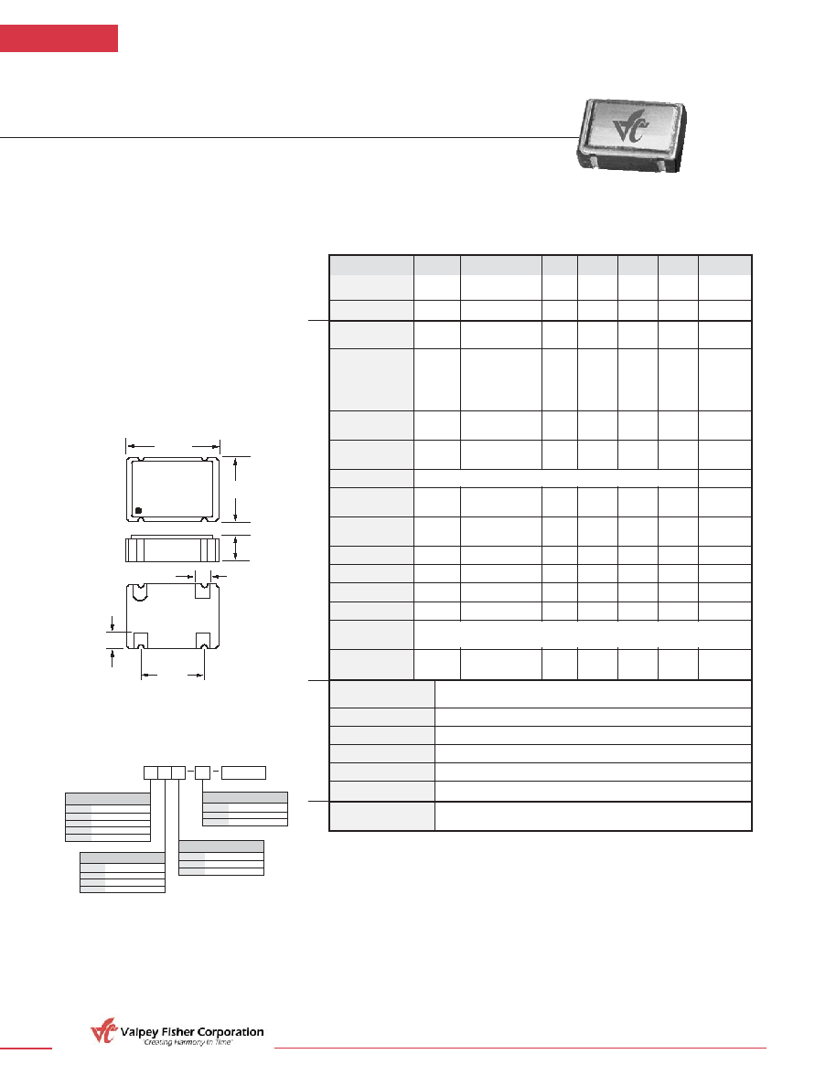
VFAC3
ACMOS/LSTTL Compatible
Surface Mount Clock Oscillators
F E AT U R E S
∑
Very Low Phase Jitter
∑
Wide Frequency Range
∑
Miniature Ceramic Package
∑
EMI Shielded
∑
Tight Duty Cycle Available
∑
Wide Temperature Range Available
∑
Tristate Control Standard
Parameter
Symb
Condition
Min
Typ
Max
Unit
Note
Input Break
Vcc
≠0.5
7.0
V
Down Voltage
Storage Temp.
Ts
≠55
+125
∞C
Frequency F 80 170 MHz
Range
Frequency
F/F
Overall conditions
±100
ppm
1
Stability
including:
calibration, temp.,
aging 10 yrs,
shock, vibration
Input Voltage
Vcc
4.75
5.00
5.25
V
Std.
3.15
3.30
3.45
LV Opt.
Input Current
Icc
F = 100MHz 70
mA
2
15pF load
Load
5
Duty Cycle
@1.4V
40
50
60
%
3
@ 50%Vcc
40
50
60
%
Rise/Fall Time
Tr/Tf
0.4V to 2.4V
1.5
ns
20% to 80%
Logic "1" Level
Voh
Max Load
0.9Vcc
V
Logic "0" Level
Vol
Max Load
0.1Vcc
V
Start≠up Time
Ts
15
ms
Phase Jitter
1
1
ps
fj>1KHz
Tristate Function
Enable/ 100
ns
4
Disable Time
Operating
Temperature Range
0∞C to +70∞C (≠40∞C to +85∞C available)
Mechanical Shock
Per MIL≠STD≠202, Method 213, Cond. E
Thermal Shock
Per MIL≠STD≠883, Method 1011, Cond. A
Vibration
Per MIL≠STD≠883, Method 2007, Cond. A
Soldering Conditions
260∞C, for 10s, Max. or 230∞C, for 90 sec
Hermetic Seal
Leak rate less than 5 x 10
≠8
atm.cc/s of helium
Pin Out
Pin #1≠Tristate Control
Pin #3≠Output
Pin #2≠Ground, Case
Pin #4≠Vcc
10 LSTTL gates or 30pF Typ, 50pF Max.,
Absolute
Max. Ratings
Electrical
Environmental and Mechanical
Electrical
Connections
Input HIGH (>2.5V) or floating: ACTIVE
Input LOW (<0.5V): INFINITE IMPEDANCE
0.303"
(7,7mm)
VFAC3
125.000MHz
BO1H
1
2
4
3
0.206"
(5,2mm)
0.200"
(5,08mm)
0.090"
(2,29mm)
0.045"
(1,143mm)
0.050"
(1,27mm)
Notes:
1. Standard frequency stability (±20, ±25, ±50, others available).
2. Current is load and frequency dependent.
3. Tighter duty cycle available.
4. Some versions enable time 10ns.
5. 50pF Max drive available, frequency an Vcc dependant
All specifications are subject to change without notice.
All dimensions are typical unless otherwise specified.
OIO/C05
09/02