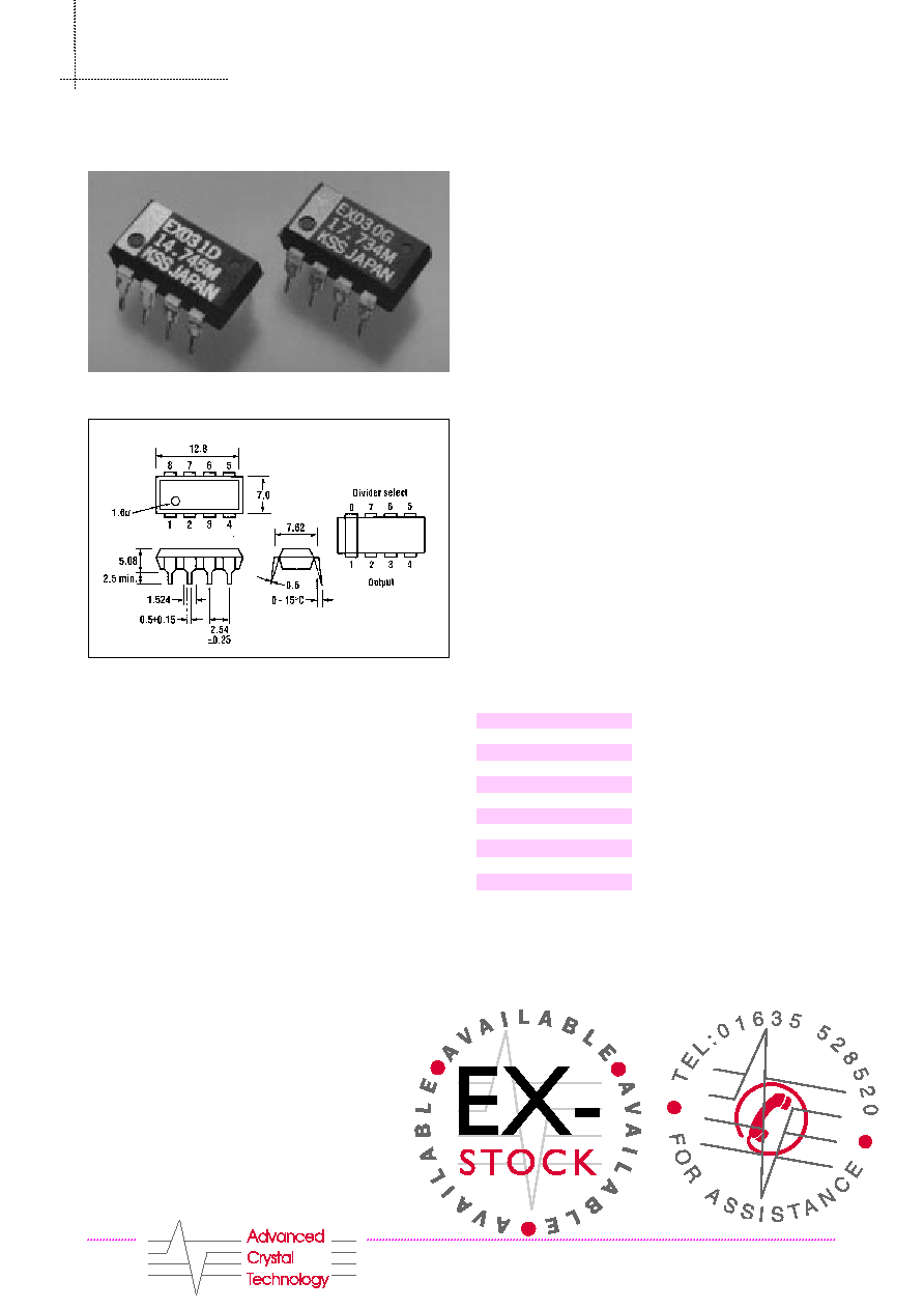
KSS-EXO-3 Series
Dimensions (mm)
Pin Connections
1.F
Outputs the original frequency (fo) of the internal quartz
crystal.
2.D
Outputs the frequency of programmed dividing ratio (fo/2
n
).
3.ST
Possible to be oscillated when set to HIGH level and
stopped in oscillation when set to LOW level. When this
function is not needed, be sure to set the STANDBY pin to
the HIGH level.
4. Gnd
5.A, 6.B & 7.C
Used to program the dividing ratio for the original frequency.
8.V
DD
Features
∑ Frequency range 46.875kHz-20MHz
∑ Supply voltage range 3 to 6V
∑ Starting time <1.5mS
∑ Ultrasonic cleaning is available
∑ Suitable for various automatic assembly
machines
∑ Low current consumption (CMOS IC structure)
∑ Standby function included
∑ High in noise margin
∑ Usable with no adjustment
∑ Most frequencies held ex-stock
∑ SMD version, see Seiko Epson
Description
The KSS-EXO-3 is a super-small CMOS crystal clock
oscillator in an 8-pin dip package equipped with a
Programmable Frequency Divider. Division
1
/
2
to
1
/
2
8
simultaneously with the original frequency can be achieved
at the user's freedom with this revolutionary device.
Composed of an AT-cut oscillator and a specially designed
CMOS IC divider, this device realises a wide range of
supply voltage, lower power consumption, high speed
operation and provides a standby function to meet most of
the user's needs. This extraordinary device can utilise
various pick & place machinery, replacing traditional
oscillators.
Standard Frequencies Ex-Stock (MHz)
Cr ystal Oscillators - KSS Kinseki
C M O S P R O G R A M M A B L E F R E Q U E N C Y D I V I D E R
T E L : + 4 4 1 6 3 5 5 2 8 5 2 0 FA X : + 4 4 1 6 3 5 5 2 8 4 4 3
EXO-3C/12.00
EXO-3C/12.288
EXO-3C/12.80
EXO-3C/14.31818
EXO-3C/14.7456
EXO-3C/16.00
EXO-3C/16.384
EXO-3C/17.73447
EXO-3C/19.6608
EXO-3C/20.00
EXO-3C/24.00
T E L : + 4 4 1 6 3 5 5 2 8 5 2 0 FA X : + 4 4 1 6 3 5 5 2 8 4 4 3
Cr ystal Oscillators
C M O - S P R O G R A M M A B L E F R E Q U E N C Y D I V I D E R
Frequency Accuracy
∑ ACT-EXO-3C = ±100ppm
∑ ACT-EXO-3D = ±500ppm
∑ ACT-EXO-3E = ±1000ppm
Handling Notes
Since this KSS-EXO type crystal clock oscillator employs a
CMOS IC integrated with a protection circuit for static
electricity, please handle only in an anti static environment.
No by-pass capacitor is inserted between the power supply
stage (V
DD
-Gnd). To protect from overvoltage and
overcurrent due to power supply noise, provide a capacitor
(above 0.01µF) as close as possible to the V
DD
-Gnd pin.
If V
DD
is applied to Pin 4, a Gnd pin, mistaken as Pin 8 (V
DD
),
ot an inverse current is applied to the device, it casuses an
internal destruction or no oscillation in some cases. To avoid
this, strict care should be taken over correct pin connection.
KSS-EXO-3 Series Absolute Maximum Ratings
Parameter
Symbol Specification
Power supply (V)
V
DD
-0.5 to +7.0V
Input voltage (V)
V
I
-0.3 to V
DD
+0.3V
Output current (mA)
I
0
±25mA
Storage Temp. range (∞C)
T
STG
-55 to +125∞C
Operating Conditions
Parameter
Symbol Specification
Min. Typ.
Max.
Supply voltage (V)
V
DD
3.0V
5.0V
6.0V
Operating temp. range
T
OPR
-10∞C
25∞C
70∞C
Characteristics (V
DD
=5.0V, C
L
=50pF, Ta = 25∞C)
Parameter
Symbol Condition
Min.
Typ.
Max.
"H" Input voltage (V)
V
IH
3.6V
"L" Input voltage (V)
V
IL
0.8V
"H" Output voltage (V)
V
OH
I
OUT
=-20µA
4.75V
I
OUT
=4mA
4.5V
"L" Output voltage (V)
V
OL
I
OUT
=-20µA
I
OUT
=4mA
Output rise time (Sec.)
T
TLH
10nS
15nS
Output fall time (Sec.)
T
TLH
10nS
15nS
Input leakage current (A)
I
I
V
IN
= V
DD
or Gnd
±1.0µA
V
DD
set up time
T
VU
1.5mS
ST set up time (Sec.)
T
STU
1.5mS
Duty ratio (%)
T1/T2
40/60%
60/40%
Power supply current
I
DD
20.0mA
Standby current
I
ST
10µA
Dividing
ratio

Cr ystal Oscillators
C M O S P R O G R A M M A B L E F R E Q U E N C Y D I V I D E R
T E L : + 4 4 1 6 3 5 5 2 8 5 2 0 FA X : + 4 4 1 6 3 5 5 2 8 4 4 3
KSS-EX0-3 Series Standard Frequencies
0
(Original Frequency)
0/2n
(Divided Waveform)
1
/
2
0
1
/
2
1
/
2
2
1
/
2
3
1
/
2
4
1
/
2
5
1
/
2
6
1
/
2
7
1
/
2
8
(MHz)
(MHz)
(MHz)
(MHz)
(kHz)
(kHz)
(kHz)
(kHz)
(kHz)
12.00
6.00
3.00
1.50
750.00
375.00
187.50
93.75
46.875
12.288
6.144
3.072
1.536
768.00
384.00
192.00
96.00
48.00
12.80
6.40
3.20
1.60
800.00
400.00
200.00
100.00
50.00
14.31818
7.15909
3.579545
1.789772
894.88
447.44
223.72
111.875
55.9375
14.7456
7.3728
3.6864
1.8432
921.60
460.80
230.40
115.20
57.60
16.00
8.00
4.00
2.00
1000.00
500.00
250.00
125.00
62.50
17.734476
8.867238
4.433619
2.216809
1108.40
554.20
227.10
138.55
69.275
18.432
9.216
4.608
2.304
1152.00
576.00
228.00
144.00
72.00
19.6608
9.8304
4.9152
2.4576
1228.80
614.40
307.20
153.60
76.80
20.00
10.00
5.00
2.50
1250.00
625.00
312.50
156.25 78.125
Setting of Dividing Output
Input
Output
Select
ST
F
D
C
B
A
(Original frequency)
(Divided waveform)
X
X
X
L
L
L
L
L
L
H
Fo/2
1
L
L
H
H
Fo/2
2
L
H
L
H
Fo/2
3
L
H
H
H
f
0
clock
Fo/2
4
H
L
L
H
Fo/2
5
H
L
H
H
Fo/2
6
H
H
L
H
Fo/2
7
H
H
H
H
Fo/2
8

T E L : + 4 4 1 6 3 5 5 2 8 5 2 0 FA X : + 4 4 1 6 3 5 5 2 8 4 4 3
Cr ystal Oscillators
C M O S P R O G R A M M A B L E F R E Q U E N C Y D I V I D E R
KSS-EX0-3 Series
Environmental and Mechanical
Characteristics
Parameter
Description
Shock
100G, 1/2 sine wave, 0.35mS
shock pulse, one each to three
directions.
Vibration
(1) 10 to 55Hz, amplitude 1.5mm
one hour each to three directions
(2) 50 to 2000Hz, acceleration 20G
one hour each to three directions.
Solder heat resistance 260∞C, dip to 1mm from the
bottom of mold in soldering tank
for 10 secs.
Solvent resistance
Free from problems of appearance
and sealing after dipping into
Fronsolve for 90 secs.