Features
∑ Output frequencies up to 777.60 MHz
∑ Jitter Generation OC-192 compliant
∑ Jitter transfer per GR-253-CORE
∑ Single 5 or 3.3 Vdc supply
∑ Locked to specified Input frequency, e.g. 8 kHz
∑ 1" x 0.8" x 0.25", Surface Mount (FR4 base)
Applications
∑ SONET / SDH / ATM
∑ DWDM / FDM
∑ DSL-PON Interconnects
∑ FEC (Forward Error Correction)
Product Data Sheet
FX-104
Frequency Translator
FX-104 Frequency Translator
Vectron International ∑
267 Lowell Road, Hudson, NH 03051 ∑ Tel:
1-88-VECTRON-1 ∑ Web:
www.vectron.com
Performance Characteristics
Description
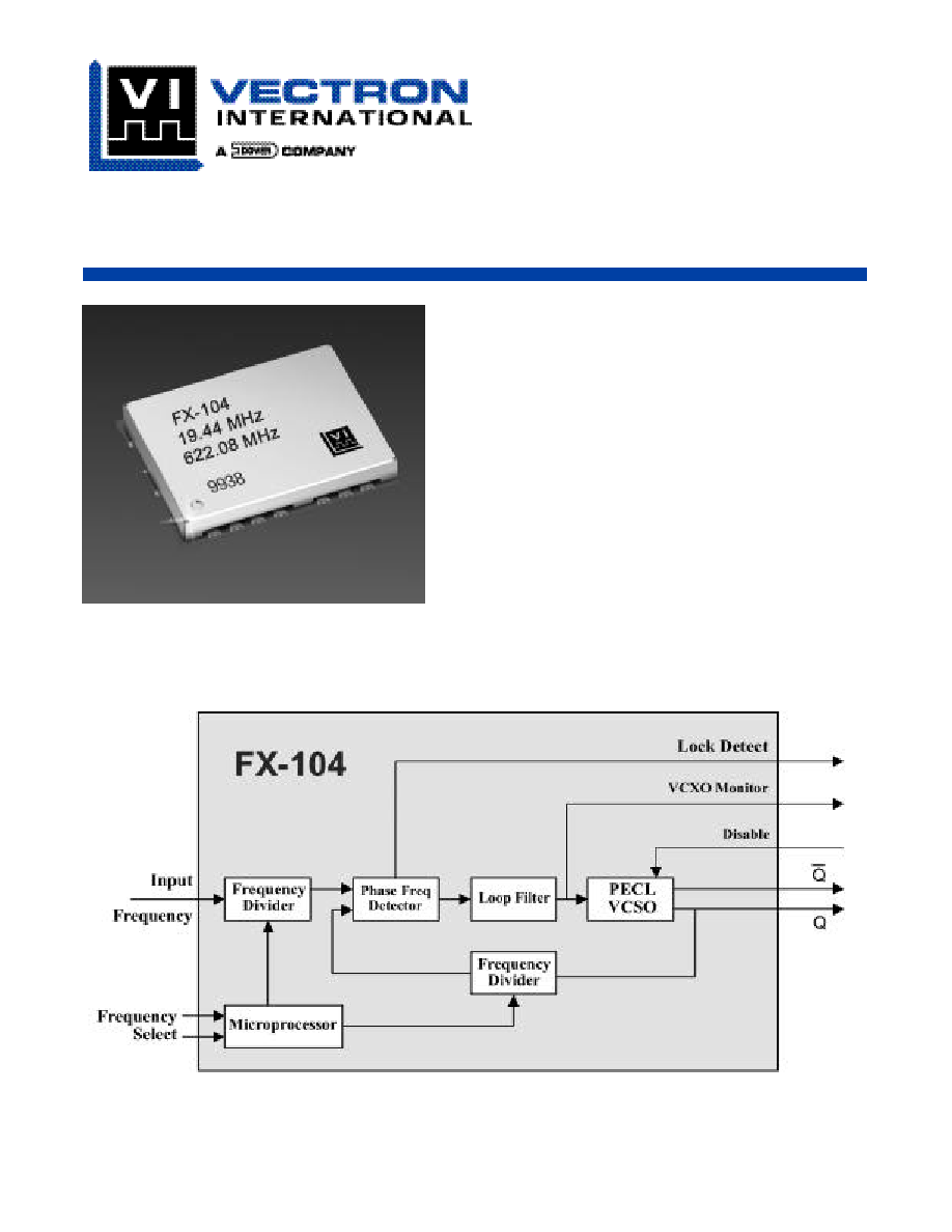
Vectron's FX-104 is a SAW based frequency translator
which is used to translate any input frequency such as
8 kHz, 1.544 MHz, 2.048 MHz, 19.440 MHz etc. to any
specific frequency from 170 MHz to 777.6 MHz. The
input frequency does not have to be a 50/50% duty
cycle and as an example can be an 8 kHz signal with a
logic high "on time" of only 1us, such as a BITS clock.
The FX-104 also has the ability to translate any of 1 to
4 different input frequencies to one common output fre-
quency, such as input frequencies of 8 kHz and 1.544
MHz and 19.44 MHz and any other frequency between
333 Hz and 170 MHz translating them to any specific
output frequency from 170 MHz to 777.600 MHz.
The "Input Frequency tracking capability" is the total
amount of input frequency deviation in which the FX-
104 is guaranteed to track or translate. As an example,
a typical input clock would be 8 kHz ±20 ppm. The FX-
104 is guaranteed to track at least ±40 ppm of error over
temperature/ aging/ power supply and is more than
twice what most applications require. The PLL control
voltage is brought out through a 470K ohm resistor. This
would allow for the use of external circuitry (analog
comparators or an A/D converter plus a processor) to
detect when the control voltage is getting close to the
limits of the pull range.
Output Frequencies
155.52
777.6
MHz
Supply Voltage,
C = 5 Vdc
V
cc
4.75
5.00
5.25
Vdc
D = 3.3 Vdc
V
cc
3.15
3.30
3.45
Vdc
Supply Current
I
cc
95
125
mA
Input Signal,
A = HCMOS
CLKIN
HCMOS
---
D = PECL
CLKIN
PECL
---
OUTPUT,
F = Comp PECL
---
---
PECL
---
---
V
OL
V
OL
V
cc
-1.95
V
cc
-1.63
V
V
OH
V
OH
V
cc
-0.98
V
cc
-0.75
V
Rise/Fall Time (20% to 80%)
t
R
/t
F
250
400
ps
Output Symmetry
Sym
45
49/51
55
%
Jitter Generation, rms
(12 kHz to 20 MHz)
0.23
1
ps
Jitter Generation, rms
(cycle to cycle method)
3
5
ps
Jitter Transfer, GR-253-CORE sec 5.6.2.1.2
0.1
dB
Input Frequency Tracking Capability
(Can translate a Stratum 1,2,3,3E,4
APR
±40
ppm
or SONET Min source)
Operating Temperature
Temp Range C = 0∞C to +70∞C
Temp Range F = -40∞C to +85∞C
Size
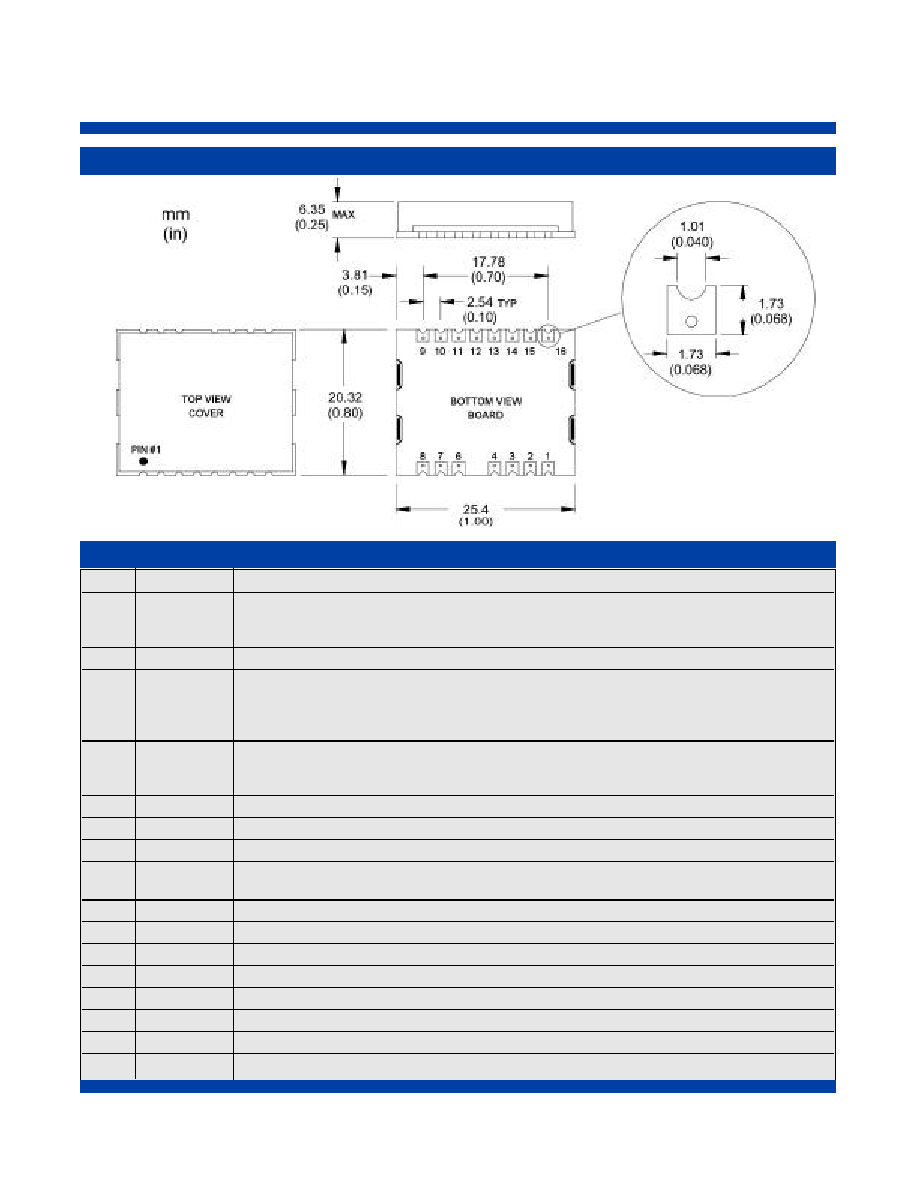
25.4 x 20.32 x 6.35 mm (1.0" x 0.8" x 0.25")
Parameter
Symbol
Min
Typical
Max
Unit
Vectron International ∑
267 Lowell Road, Hudson, NH 03051 ∑ Tel:
1-88-VECTRON-1 ∑ Web:
www.vectron.com
FX-104 Frequency Translator
Pin
Symbol
Function
1
CLKIN
Input Frequency - The FX-104 series AC couples the input, this means the unit is capable of
handling HCMOS, LvHCMOS, PECL and LvPECL input signals.
(For Input Frequencies below 1 MHz only HCMOS and LvHCMOS are supported)
2
GND
Ground
3
LD
Lock Detect
(output)
Logic "1" indicates a locked condition
Logic "0" indicates that no input signal is present or the input signal has moved out of the
lock range.
4
Monitor
PLL/ VCXO control voltage
(Output)
Under locked conditions, should be >0.3V and <3.0V for the 3.3 volt option or >0.5V and
<4.5V for the 5 volt option. Input frequency may be out of range if voltage exceeds these limits.
5
---
Missing
6
NC
No Connection
7
GND
Ground
8
Enable
No connect = Output enabled
Disable
Logic "0"
= Output disabled
9
Out
Output
10
COUT
Complementary Output
11
NC
No Connection
12
Select A
Do not Exceed Vcc
13
Select B
Do not Exceed Vcc
14
NC
No Connection
15
GND
Ground
16
V
cc
Power Supply Voltage (5 Vdc or 3.3Vdc)
Pin Out
Outline Drawing
FX-104 Frequency Translator
Vectron International ∑
267 Lowell Road, Hudson, NH 03051 ∑ Tel:
1-88-VECTRON-1 ∑ Web:
www.vectron.com
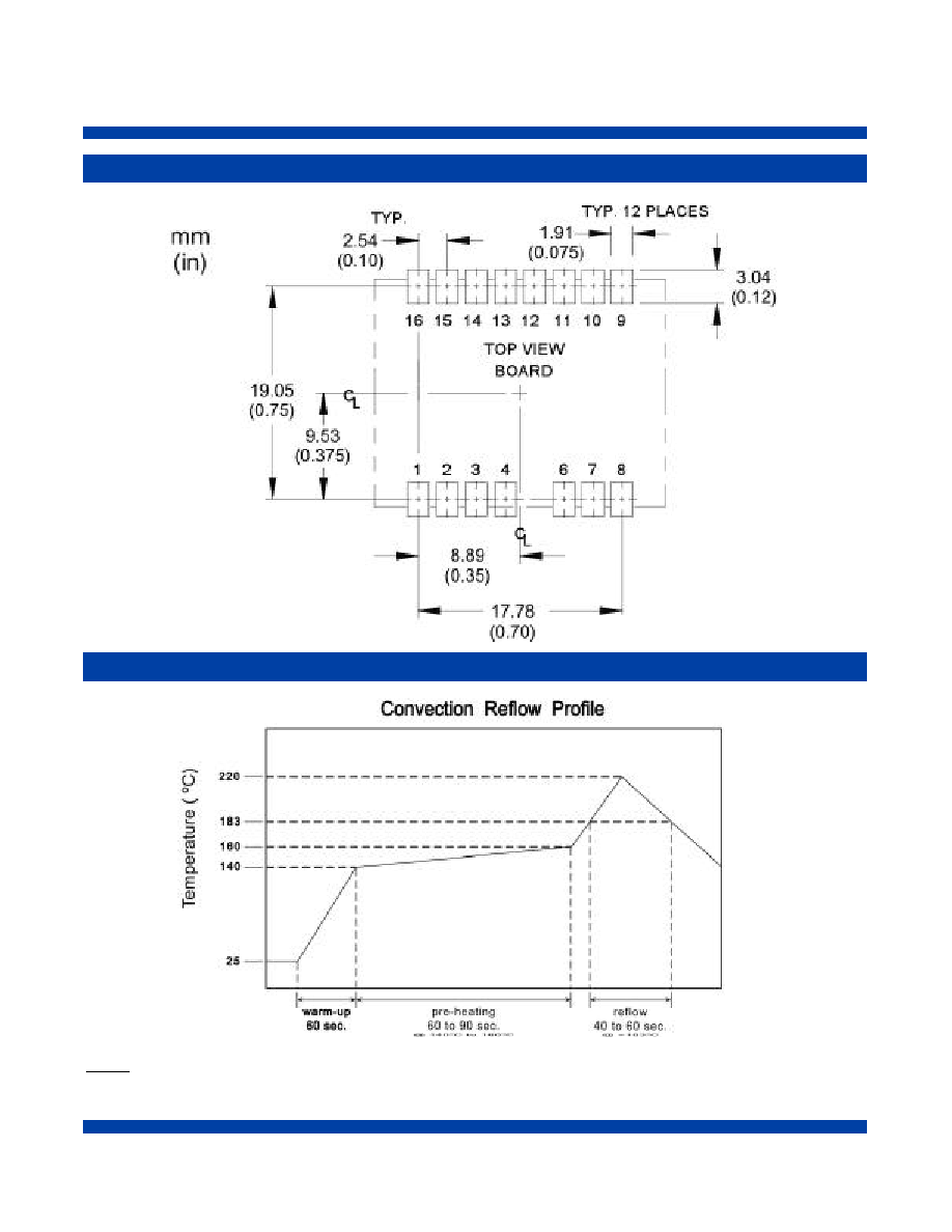
Pad Layout
Recommended Reflow Profile
NOTE: The FX-100 series should not be subjected to a wash process that will immerse it in solvents. NO CLEAN is the rec-
ommended procedure. The FX-100 series has been designed for pick and place reflow soldering. The suggested reflow pro-
file is shown above. The FX-100 series may be reflowed once, and should not be reflowed in the inverted position.

Vectron International ∑
267 Lowell Road, Hudson, NH 03051 ∑ Tel:
1-88-VECTRON-1 ∑ Web:
www.vectron.com
FX-104 Frequency Translator
Standard Shipping Method
The Standard ship method for volume production of the
FX-100 series is in a matrix tray. These trays are 100%
recyclable. The trays also offer the added feature that
they can be continuously feed into a pick-n-place
machine eliminating the down time required with tape-
n-reel.
Handling Precautions
Although protection circuitry has been designed into this
d ev i c e, proper precautions should be taken to avo i d
exposure to electrostatic discharge (ESD) during han-
dling and mounting. VI employs a human-body model
(HBM) for ESD-susceptibility testing and protection
design eva l u a t i o n .
ESD voltage thresholds are dependent on the circuit
p a rameters used to define the mode. The HBM ESD
threshold presented here was obtained by using para-
meters where resistance = 1500 ohms, capacitance =
100pf)
ESD Threshold Voltage
Model
Threshold
Unit
Human Body (HBM)
500
V min