
Product Highlights
The MI-Series is designed for
military applications and is based
on Vicor's 1st Generation family of
zero-current/zero-voltage switching,
component level DC-DC converters.
Operating at frequencies in excess
of 1MHz, the MI-Series offers
state-of-the-art performance in
terms of power density, efficiency,
noise, ease of use, and reliability.
All units are manufactured in ISO
9001-registered facilities. Full
epoxy encapsulation in Vicor's
industry standard package
enables the MI-Series to meet
MIL-STD-810 environmental
requirements for humidity,
fungus, salt, fog, explosive
atmosphere, acceleration,
vibration, and shock. (See page 32.)
Standard features such as wide
output trimming/programming,
current limiting, remote sense,
output inhibit, and latching
OVP and OTP combine to offer
a high degree of protection,
versatility, and reliability for
military power systems.
MI-200
TM
PARAMETER
MIN
TYP
MAX
UNITS
TEST CONDITIONS
Input Characteristics
Input voltage range
See input voltage chart
No load power dissipation
1.35
2.0
Watts
Output Characteristics
Set point accuracy
0.5
1.0
% Vnom
Load/line regulation
0.05
0.2
% Vnom
LL to HL, 10% to FL
0.2
0.5
% Vnom
LL to HL, NL to 10%
Output temperature drift
0.01
0.02
%/∞C
Output noise - pp
1.0
1.5
% Vnom
Whichever is greater
100
150 mV 20MHz
BW
Output voltage trimming
(1)
50
110
% Vnom
Remote sense compensation
0.5
Vdc
OVP set point
(2)
115
125
135
% Vnom
Latching
Current limit
105
125
% Inom
Auto restart
Short circuit current
(3)
20
130
% Inom
Control Pin Characteristics
Gate-in high threshold
6
Vdc
Gate-in low threshold
0.65
Vdc
Gate-in low current
6
mA
Power sharing accuracy
0.95
1.05
Isolation Characteristics
Isolation (input to output)
3,000
Vrms
Isolation (output to baseplate)
500
Vrms
Isolation (input to baseplate)
1,500
Vrms
Input/output capacitance
50
75
pF
Environmental (MIL-STD-810)
Altitude - method 500.2
70,000
feet
Procedure II
Humidity - method 507.2
86 / 240
% / hours
Procedure 1, cycle 1
Acceleration - method 513.3
9
g's
Procedure 2
Vibration - method 514.3
20
g's
Procedure 1, category 6
Shock - method 516.3
40
g's
Procedure 1
Reliability (MIL-HDBK-217F)
25∞C Ground Benign: G.B.
2,478,477
hours
50∞C Naval Sheltered: N.S.
584,920
hours
65∞C Airborne Inhabited Cargo: A.I.C.
483,303
hours
Thermal Characteristics
Efficiency
80-90
%
Baseplate to sink
0.07
∞C/W
With thermal pads
Thermal shutdown
90
95
105
∞C
Latching
Baseplate operating temperature
+85
∞C
See product grade
Storage temperature
+100
∞C
See product grade
Mechanical Specifications
Weight
6.0 (170)
ounces (grams)
Converter/Booster Specifications
(At TBP = 25∞C, nominal line and 75% load, unless otherwise specified)
Features
Military DC-DC Converters 50 to 100W
(1)
10V, 12V, and 15V outputs, standard trim range ±10%. Consult factory for wider trim range.
(2)
No over temperature or voltage protection in booster modules.
(3)
Output voltages of 5V or less incorporate foldback current limiting; outputs of 10V and above provide
constant current limiting.
Inputs:
28Vdc per MIL-STD-704D/E
155Vdc per MIL-STD-1399A
270Vdc per MIL-STD-704D/E
Single output: 2 ≠ 48Vdc
Up to 23W/in
3
MIL-STD-810 environments
Up to 90% efficiency
Remote sense
Current limit
OVP and thermal shutdown
Power boosters for
higher power outputs
ZVS/ZCS power architecture
Low noise FM control
Size: 4.6" x 2.4" x 0.5"
(116,8 x 61,0 x 12,7mm)
}
MI-200 10/02 1 of 2
Configuration Chart
Input Voltage
Nominal
Range
Transient
2 =
28V
18 ≠ 50V
(1)
60V
5 = 155V
100 ≠ 210V
230V
6 = 270V
125 ≠ 400V
(2)
475V
7 = 165V
100 ≠ 310V
MI - 2
-
Semi-custom driver and booster
modules available: Consult factory.
(1) 16V operation at 75% load.
(2) These units rated at 75%
load from 125-150Vin:
MI-26Z-xV
MI-26Y-xV
MI-260-xW
28Vdc input per MIL-STD 704D/E
155Vdc input per DOD-STD-1399A
270Vdc input per MIL-STD-704D/E
Product Grade Specifications
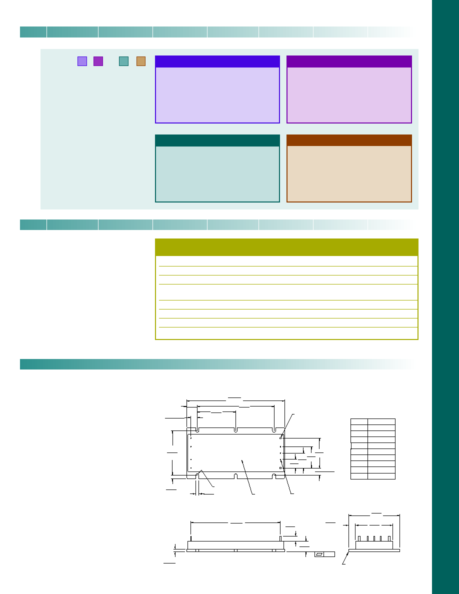
+0.030 (0,76)
-0.000 (0)
Product ID
this surface
FULL R
5
6
7
8
9
4
3
2
1
Pin #
1
2
3
4
5
6*
7*
8*
9
Function
+In
Gate In
Gate Out
-In
+Out
+Sense
Trim
-Sense
-Out
* Do not connect on
Booster modules
Aluminum Base
.01
0.040 (1,0) Dia (7) places
Solder plate
over copper alloy
0.080 (2,0) Dia (2) places
Solder plate
over copper alloy
0.30
±
0.015
(7,6)
±
(0,38)
1.80
(45,7)
4.20
0.50
0.22
(5,6) MIN
0.12
4.60
2.40
1.75
0.30
0.15
(3,8)
2.10
(53,3)
0.40
(10,2)
0.35
±
0.015
(8,9)
±
(0,38)
1.40
(35,6)
1.00
(25,4)
0.70
(17,8)
3.60
MI-200 Mechanical Drawing
0.50
(12,7)
0.15
(3,8)
MI-200
(116,8)
(91,4)
(3,0)
(7,6)Min
(12,7)
(61,0)
(44,5)
(106,7)
*Test data available for review or download from vicorpower.com
Mechanical Drawing
Output Power/Current
5V
<5V
Y
=
50W
10A
X
=
75W
15A
W
=
100W
20A
V
=
--
o
30A
For additional power, 100W and 75W booster
modules available. Change MI-2xx-xx to MI-Bxx-xx.
Product Grade
Operating Temp.
I
=
-40∞C to +85∞C
M
=
-55∞C to +85∞C
PARAMETER
PRODUCT GRADE
I - Grade M - Grade
Storage temperature
-55∞C to +100∞C
-65∞C to +100∞C
Operating temperature (baseplate)
-40∞C to +85∞C
-55∞C to +85∞C
Power cycling burn-in
12 hours, 25 cycles
96 hours, 200 cycles
Temperature cycled with power off
48 hours, 12-16 cycles
48 hours, 12-16 cycles
-55∞C to +100∞C
-65∞C to +100∞C
Test data supplied at these temperatures*
-40∞C, +80∞C
-55∞C, +80∞C
Warranty
2 years
2 years
Environmental compliance
MIL-STD-810
MIL-STD-810
Derating
NAVMAT P-4855-1A
NAVMAT P-4855-1A
Output Voltage
Z = 2V
T = 6.5V
N = 18.5V
Y = 3.3V
R = 7.5V
3 = 24V
0 = 5V
M= 10V
L = 28V
X = 5.2V
1 = 12V
J = 36V
W= 5.5V
P = 13.8V
K = 40V
V = 5.8V
2 = 15V
4 = 48V
MI-200 10/02 2 of 2