12
1-800-735-6200
70
Product Grade/
Product Grade/
Operating Temp. Storage Temp.
E = -10įC to +85įC
E = -20įC to +100įC
C = -25įC to +85įC
C = -40įC to +100įC
I = -40įC to +85įC
I = -55įC to +100įC
M = -55įC to +85įC
M = -65įC to +100įC
Overtemperature shutdown 95įC typical
(recycle power to restart).
Converter Selection Chart
VI-2
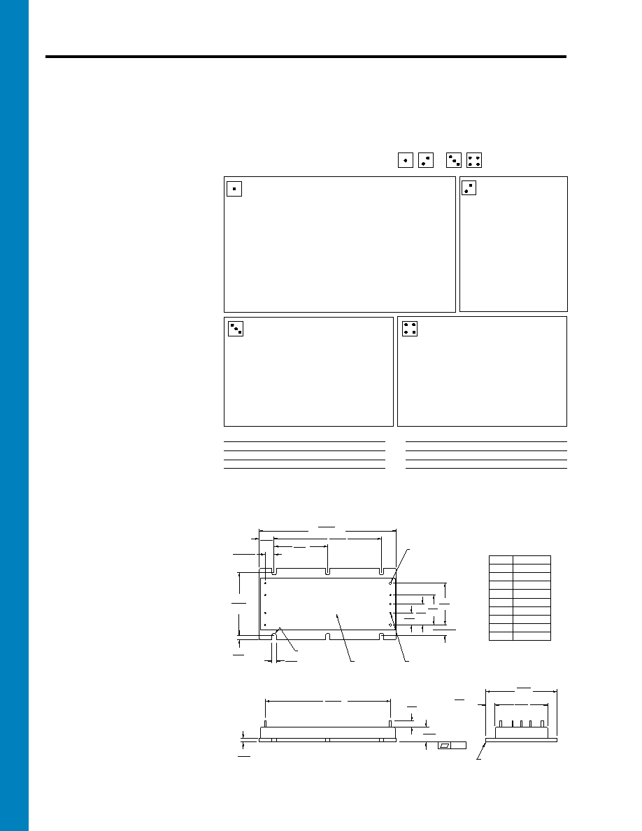
Mechanical Drawing
Features
s Up to 50W/Cubic Inch
s UL, CSA, T‹V, VDE, BABT,
AUSTEL
s Up to 90% Efficiency
s Size: 4.6" x 2.4" x 0.5"
(116,8 x 61,0 x 12,7)
s Remote Sense and Current Limit
s OVP, Thermal Shutdown
s Logic Disable
s Wide Range Output Adjust
s Compatible Power Booster Modules
s ZCS Power Architecture
s Low Noise FM Control
s CE Marked
VI-200
DC-DC Converters
50 to 200 Watts
Product Highlights
The VI-200 Family, with over 8 million
shipped, is Vicor's first generation of
"zero-current-switching" component-level
DC-DC converters.
Operating at frequencies up to 2 MHz,
VI-200 Family Converters offer
exceptional power density, efficiency,
noise performance, reliability and ease of
use. Power Boosters provide a simple, cost
effective, off-the-shelf solution for higher
power output requirements. One or more
boosters may be used to create synchronous
arrays capable of supplying several
kilowatts of output power.
The flexibility of Vicor's power components
is also available in half-size, half-power
VI-J00 MiniMods. (pg. 72)
Packaging Options
SlimModsTM, high power density,
flangeless packages and FinModsTM,
featuring integral finned heatsinks.
SlimMod: Option suffix: - S
Example: VI - 2XX - XX
- S
FinMod: Option suffix: - F1 and - F2
Examples:
VI - 2XX - XX -
F1, 0.75" height
VI - 2XX - XX -
F2, 1.00" height
Max. Output For
5V Outputs
> 5V Outputs
< 5V Outputs
(1)
75W
75W
15A
(2)
150W
150W
30A
(3)
100W
100W
20A
* Brownout 75% of rated load; transient voltage for 1 second.
Max. Output For
5V Outputs
> 5V Outputs
< 5V Outputs
(4)
200W
200W
40A
(5)
150W
200W
40A
(6)
75W
100W
20A
Output Power/Current
V
OUT
5V
V
OUT
< 5V
Y
=
50W
Y
=
10A
X
=
75W
X
=
15A
W
=
100W
W
=
20A
V
=
150W
V
=
30A
U
=
200W
U
=
40A
For additional output power use "Boosters".
Change (VI-2xx-xx) to (VI-Bxx-xx).
Output Voltage
Z =
2V
2 =
15V
Y = 3.3V
N = 18.5V
0 =
5V
3 =
24V
X = 5.2V
L =
28V
W = 5.5V
J =
36V
V = 5.8V
K =
40V
T = 6.5V
4 =
48V
R = 7.5V
H =
52V
M =
10V
F =
72V
1 =
12V
D =
85V
P = 13.8V
B =
95V
Input Voltage
Nominal
Range
Brownout
/
Transient
*
0
=
12V
10 -
20V
(1)
n/a
22V
1
=
24V
21 -
32V
(4)
18V
36V
W =
24V
18 -
36V
(2)
n/a
n/a
2
=
36V
21 -
56V
(3)
18V
60V
3
=
48V
42 -
60V
(4)
36V
72V
N =
48V
36 -
76V
(4)
n/a
n/a
4
=
72V
55 - 100V
(4)
45V
110V
T
=
110V
66 - 160V
(2)
n/a
n/a
5
=
150V
100 - 200V
(5)
85V
215V
6
=
300V
200 - 400V
(4)
170V
425V
7
= 150/300V
100 - 375V
(6)
90V
n/a
+.030 (0,76)
-.000 (0)
Product ID
this surface
FULL R
5
6
7
8
9
4
3
2
1
Pin #
1
2
3
4
5
6*
7*
8*
9
Function
+In
Gate In
Gate Out
-In
+Out
+Sense
Trim
-Sense
-Out
* Do not connect on
Booster modules
Aluminum Base
.01
.040 (1,0) Dia (7) places
Solder plate
over copper alloy
.080 (2,0) Dia (2) places
Solder plate
over copper alloy
.30
Ī
.015
(7,6)
Ī
(0,38)
1.80
(45,7)
(106,7)
(12,7)
(5,6) MIN
(3,0)
(116,8)
(61,0)
(44,5)
(7,6) Min
.15
(3,8)
2.10
(53,3)
.40
(10,2)
.35
Ī
.015
(8,9)
Ī
(0,38)
1.40
(35,6)
1.00
(25,4)
.70
(17,8)
(91,4)
.50
(12,7)
VI-200
4.60
3.60
.15
(3,8)
4.20
.12
.22
.50
.30
2.40
1.75
Rev 3 1 of 2
For the latest Vicor Product Information: www.vicorpower.com

12
1-800-735-6200
71
VI-200 E-Grade
VI-200 C-, I-, M-Grade
PARAMETER
MIN.
TYP.
MAX.
MIN.
TYP.
MAX.
UNITS
TEST CONDITIONS
s Input Characteristics
Inrush charge
120x10
-6
120x10
-6
200x10
-6
Coulombs
Nominal line
Input reflected ripple current ≠ pp
10%
10%
I
IN
Nominal line, full load
Input ripple rejection
dB
120 Hz, nominal line
dB
2400 Hz, nominal line
No load power dissipation
1.35
2
1.35
2
Watts
s Output Characteristics
Setpoint accuracy
1%
2%
0.5%
1%
V
NOM
Load/line regulation
0.5%
0.05%
0.2%
V
NOM
LL to HL, 10% to Full Load
Load/line regulation
1%
0.2%
0.5%
V
NOM
LL to HL, No Load to 10%
Output temperature drift
0.02
0.01
0.02
% / įC
Over rated temp.
Long term drift
0.02
0.02
%/1K hours
Output ripple - pp:
2V, 3.3V
150 mV
60 mV
100 mV
20 MHz bandwidth
5V
5%
2%
3%
20 MHz bandwidth
10-48V
3%
0.75%
1.5%
20 MHz bandwidth
Trim range
1
50%
110%
50%
110%
Total remote sense compensation
0.5
0.5
Volts
0.25V max. neg. leg
OVP set point
125%
2
115%
125%
2
135%
V
NOM
Recycle power
Current limit
105%
135%
105%
125%
I
NOM
Automatic restart
Short circuit current
3
20%
140%
20%
130%
I
NOM
s Control Pin Characteristics
Gate out impedance
50
50
Ohms
Gate in impedance
10
3
10
3
Ohms
Gate in open circuit voltage
6
6
Volts
Use open collector
Gate in low threshold
0.65
0.65
Volts
Gate in low current
6
6
mA
Power sharing accuracy
0.95
1.05
0.95
1.05
s Dielectric Withstand Characteristics
Input to output
3,000
3,000
V
RMS
Baseplate earthed
Output to baseplate
500
500
V
RMS
Input to baseplate
1,500
1,500
V
RMS
s Thermal Characteristics
Efficiency
78-88%
80-90%
Baseplate to sink
0.2
0.2
įC/Watt
With Vicor P/N 01777
Thermal shutdown
4
90
95
105
90
95
105
įC
Cool and recycle power
(Drivers only)
to restart
s Mechanical Specifications
Weight
6.0 (170)
6.0 (170)
Ounces (Grams)
1
10V, 12V and 15V outputs, standard trim range Ī10%. Consult factory for wider trim range.
2
131% nominal for booster modules.
3
Output voltages of 3.3V or 5V incorporate foldback current limiting; all other outputs provide constant current limiting.
4
No overtemp protection in booster modules.
Converter Specifications
(typical at T
BP
= 25įC, nominal line and 75% load, unless otherwise specified)
25+20Log
(
Vin
)
Vout
30+20Log
(
Vin
)
Vout
20+20Log
(
Vin
)
Vout
Rev 3 2 of 2
For the latest Vicor Product Information: www.vicorpower.com