 | –≠–Ľ–Ķ–ļ—ā—Ä–ĺ–Ĺ–Ĺ—č–Ļ –ļ–ĺ–ľ–Ņ–ĺ–Ĺ–Ķ–Ĺ—ā: VI-LU3-EW | –°–ļ–į—á–į—ā—Ć:  PDF PDF  ZIP ZIP |
Input Characteristics
90-132/180-264Vac
U = Autoranging
Output Power/Current
V
out
5V
V
out
< 5V
S = 300W
S = 60A
P = 450W
P = 90A
M = 600W
M = 120A
Product Grade
E = 0įC to +85įC Case
C = 0įC to +85įC Case
I = -30įC to +85įC Case
Output Power/Current
V
out
5V
V
out
< 5V
Y = 50W
Y = 10A
X = 75W
X = 15A
W = 100W
W = 20A
V = 150W
V = 30A
U = 200W
U = 40A
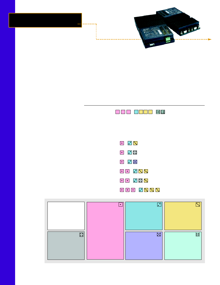
Product Highlights
If you're looking for the convenience
of a complete, low profile, agency-
approved switching power supply,
look no further. The FlatPAC combines
Vicor's workhorse VI-200 family of
DC-DC converters with a modular
package and front end subassembly to
provide from 50 to 600W of output
power from one to three outputs.
A flat plate heatsink for use in
conduction cooled applications may be
specified as an alternate to the standard
finned version by adding "CC" to the
end of the model number.
Vicor's FlatPAC is also available with
a current controlled output using
BatMod converter modules of 12, 24,
or 48Vdc outputs. This option is
specified by appending "BM" or "BC"
(for conduction cooled versions) to the
end of the FlatPAC model number.
The FlatPAC's contemporary design
allows us to configure your order
quickly and provide rapid turnaround
on standard models. It is truly a
complete power solution, enabling
you to spend more time designing your
system and less time worrying about
how to power it.
Features
Microcontroller architecture
Inputs: 115/230Vac autoranging
Meets FCC Part 15, EN55022, Class B
conducted emissions
80-90% efficiency
Any output: 1 to 95Vdc
Module enable/disable (except LU series)
UL, CSA, T‹V, VDE, BABT, CE marked
Remote sense and current limit
BUS OK and AC OK (except LU series)
40mS ride-through time
OVP and thermal shutdown
1 output; up to 200W
1 or 2 outputs; up to 400W
1, 2, or 3 outputs; up to 600W
F l a t PA C
TM
50 to 600W
Autoranging
AC-DC Switchers
FlatPAC Configuration Chart
Typical Model: V I - R U
≠
≠
Input: 115/230Vac; Output 1: 5Vdc at 200W
Output 2: 12Vdc at 200W
Output 3: 12Vdc at 200W
# of
Total Power
Part No.
Converters Dimensions
50-200W
VI-LU
≠
1
9.25" x 2.5" x 1.37"
(234,8 x 63,5 x 34,8mm)
200-400W
VI-MU
≠
2
9.25" x 4.9" x 1.37"
(234,8 x 124,5 x 34,8mm)
300-600W
VI-NU
≠
3
9.25" x 7.3" x 1.37"
(234,8 x 185,4 x 34,8mm)
100-400W
VI-PU
≠
2
9.25" x 4.9" x 1.37"
(234,8 x 124,5 x 34,8mm)
150-600W
VI-QU
≠
3
9.25" x 7.3" x 1.37"
(234,8 x 185,4 x 34,8mm)
150-600W
VI-RU
≠
3
9.25" x 7.3" x 1.37"
(234,8 x 185,4 x 34,8mm)
U
U
U
E
1
1
0
Single
Outputs:
Dual
Outputs:
Triple
Outputs:
Options
BC = BatMod/Conduction
Cooled
BM= BatMod
CC = Conduction Cooled
Output Voltage
Z 2V
M 10V
K 40V
Y 3.3V
1 12V
4 48V
0 5V
P 13.8V H 52V
X 5.2V
2 15V
F 72V
W 5.5V
N 18.5V D 85V
V 5.8V
3 24V
B 95V
T 6.5V
L 28V
R 7.5V
J 36V
Output Power
V
out
5V
V
out
< 5V
W = 100W
W = 20A
V = 150W
V = 30A
U = 200W
U = 40A
S = 300W
S = 60A
Q = 400W
Q = 80A
FlatPAC 10/02 1 of 4

FlatPAC Specifications
(Typical at 25įC, nominal line and 75% load, unless otherwise specified.)
Input Characteristics
AC line input
Autoranging
90-132/180-264Vac
Line frequency
47 to 63Hz (C-grade and E-grade)
47 to 440Hz (I-grade)
Inrush current
115Vac operation
1 converter: 16A @ peak line; 2 converters: 23A @ peak line; 3 converters: 39A @ peak line
230Vac operation
1 converter: 32A @ peak line; 2 converters: 47A @ peak line; 3 converters: 78A @ peak line
Ride-through time (full load)
90/180Vac low line
5ms minimum
115/230Vac nominal line
40ms minimum
AC fail warning time
5ms minimum (low line, full load)
AC and BUS OK (2 converter and 3 converter models only)
Off state
Vce = 70V maximum
On state
Vcesat = 0.4V maximum @ 1mA (1.5mA max.)
Module disable (2 converter and 3 converter models only, optically isolated LED input)
Continuous forward current
1 mA to 30mA
Forward voltage
1.65V max. at 30mA
Dielectric withstand
Primary to chassis GND
2,121Vdc
Primary to secondary
4,242Vdc
Secondary to chassis GND
707Vdc
Output Characteristics (applies to each output individually)
E-Grade
C-, I-Grade
MIN.
TYP.
MAX.
MIN.
TYP.
MAX
UNITS
NOTES
Setpoint accuracy
1%
2%
0.5%
1%
V
NOM
Load/line regulation
0.5%
0.05%
0.2%
V
NOM
LL to HL, 10% to Full Load
Load/line regulation
1%
0.2%
0.5%
V
NOM
LL to HL, No Load to full load
Output temperature drift
0.02
0.01
0.02
%/įC
Over rated temperature
Long term drift
0.02
0.02
%/1k hours
Output ripple
2V
150mV
60mV
100mV
p-p
20MHz bandwidth
5V
5%
2%
3%
p-p
20MHz bandwidth
10-48V
3%
0.75%
1.5%
p-p
20MHz bandwidth
Output voltage trimming
1
50%
110%
50%
110%
Total remote sense
compensation
0.5
0.5
Volts
0.25V max. neg. leg
OVP setpoint
125%
115%
125%
135%
V
NOM
Recycle power
Current limit
105%
135%
105%
125%
I
NOM
Automatic restart
Short circuit current
2
20%
140%
20%
130%
I
NOM
Thermal Characteristics
Efficiency
78-88%
80-90%
Shutdown temp. -- case
90
95
105
90
95
105
įC
Cool and recycle power to restart
Operating temp. -- case
85
85
įC
See Thermal Curves
Mechanical Specifications
Weight
3
22.4 (652)
22.4 (652)
Ounces (Grams)
Safety Agency Approvals
UL, CSA, T‹V, VDE, IEC 950, CE Marked for low voltage directive, 73/23/EEC
Environmental Characteristics/Product Grade Designators
Storage temperature
-20įC to +100įC (C-grade and E-grade)
-55įC to +100įC (I-grade)
Operating temperature (case)
0įC to +85įC (C-grade and E-grade)
-30įC to +85įC (I-grade)
EMI / EMC Characteristics (Performed on selected samples representative of the U Series FlatPac product family.)
Conducted emissions, LISN
EN 55022 and FCC R&R, Part 15, Subpart B, Class B
Electrostatic discharge
IEC 801-2, 1991, Level 4; Ī8kV Contact, Ī 15kV Air Discharge
RF radiated immunity, E-field
IEC 801-3, 1984; 27MHz to 500MHz, 3 V/M, CW
Electrical fast transients/burst
EN 61000-4-4, Level 2; Ī1kV,
Surge immunity
EN 61000-4-5, Class 3; Ī2kV Line to Ground, Ī1kV Line to Line
1
10, 12V and 15V outputs, trim range Ī10%. Consult factory for wider trim range.
2
Output voltages of 5V or less incorporate foldback current limiting, greater than 5V incorporate straight line current limiting.
3
For MU, PU series, multiply value by 2; for NU, QU, RU series, multiply value by 3.
FlatPAC 10/02 2 of 4

Thermal Curves, 5V Output
Thermal Curves, 10 to 48V Output
0
75
150
225
300
375
450
525
600
0
5
10
15
20
25
30
35
40
45
50
55
60
65
70
75
80
85
Ambient Temperature (Deg. C)
Output P
o
w
e
r (W
atts)
0
25
50
75
100
125
150
175
200
0
5
10
15
20
25
30
35
40
45
50
55
60
65
70
75
80
85
Ambient Temperature (Deg. C)
Output P
o
w
er (W
atts)
0
50
100
150
200
250
300
350
400
0
5
10
15
20
25
30
35
40
45
50
55
60
65
70
75
80
85
Ambient Temperature (Deg. C)
Output P
o
w
e
r (W
atts)
0
75
150
225
300
375
450
525
600
0
5
10
15
20
25
30
35
40
45
50
55
60
65
70
75
80
85
Ambient Temperature (Deg. C)
Output P
o
w
er (W
atts)
0
25
50
75
100
125
150
175
200
0
5
10
15
20
25
30
35
40
45
50
55
60
65
70
75
80
85
Ambient Temperature (Deg. C)
Output P
o
w
er (W
atts)
0
50
100
150
200
250
300
350
400
0
5
10
15
20
25
30
35
40
45
50
55
60
65
70
75
80
85
Ambient Temperature (Deg. C)
Output P
o
w
er (W
atts)
Application Circuits
MOD DIS ≠
MOD DIS +
AC OK ≠
AC OK +
BUS OK ≠
BUS OK +
Internal
Supervisory
Circuits
(Optocouplers)
AC Mains
Earth Ground
L1
L2/N
GND
2-Up
and
3-Up
1-Up
V
LINE
90 (180) Vac
AC Line
Interrupted
AC
Line
AC OK
BUS OK
T0 T1
T2
T3
T4
Conditions: Full Load 90 (180) Vac, AC Line
Time Interval
Min
Typ
Max
Units
Notes
T0-T1
0
0.1
1.0
ms
T2-T3
0
40
≠
ms
Ride-through time
T2-T4
5
≠
≠
ms
Hold-up time
T3-T4
5
≠
≠
ms
AC fail warning time
Resistor Values for Trimming Standard Output Voltages
Nom. Output Voltage
5V
12V
15V
24V
28V
48V
Trim Range
R1(k
)
0.953
15.8
22.1
41.2
48.7
90.9
+10%, -10%
R2(k
)
90
90
90
90
90
90
R2
+S
Trim
10K
R1
+ Vout
Vout RTN
+O
≠O
≠S
AC Mains Connections
Power Up and Power Down Sequencing
Output Trimming
Ambient Temperature (Deg. C)
Ambient Temperature (Deg. C)
Ambient Temperature (Deg. C)
Ambient Temperature (Deg. C)
Ambient Temperature (Deg. C)
Ambient Temperature (Deg. C)
LU Series
MU, PU Series
NU, QU, RU Series
LU Series
MU, PU Series
NU, QU, RU Series
Output Power (W
atts)
Output Power (W
atts)
Output Power (W
atts)
Output Power (W
atts)
Output Power (W
atts)
Output Power (W
atts)
FREE AIR
50 LFM
100 LFM
250 LFM
500 LFM
750 LFM
1000 LFM
FREE AIR
50 LFM
100 LFM
250 LFM
500 LFM
750 LFM
1000 LFM
FlatPAC 10/02 3 of 4
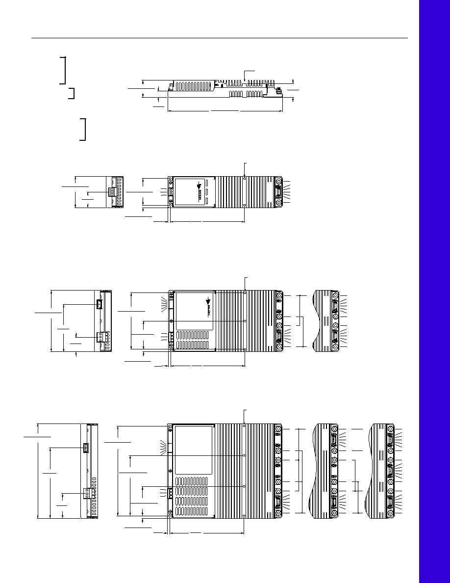
Mechanical Drawings
10
11
12
13
14
15
16
7
8
9
MOUNTING HOLE
Ý 0.15
Ī
0.01 THRU
4 PLACES
2.156
Ī
0.010
54.76
Ī
0.25
0.192
Ī
0.010
4.88
Ī
0.25 0.18
4.57
6.00
152.4
2.540
Ī
0.030
64.52
Ī
0.76
1.27
32.26
OUTPUT 1
MOUNTING HOLE
Ý 0.15
Ī
0.01 THRU
5 PLACES
10
16
10
11
12
13
14
15
16
10
11
12
13
14
15
16
10
11
12
13
14
15
16
7
8
9
1
2
3
4
5
6
4.562
Ī
0.010
115.87
Ī
0.25
2.281
Ī
0.010
57.94
Ī
0.25
0.199
Ī
0.010
5.05
Ī
0.25
0.18
4.57
6.00
152.4
4.960
Ī
0.030
125.98
Ī
0.76
3.83
97.16
1.17
29.72
OUTPUT 1
OUTPUT 2
OUTPUT 1
+
≠
10
11
12
13
14
15
16
10
16
10
11
12
13
14
15
16
10
11
12
13
14
15
16
10
11
12
13
14
15
16
10
11
12
13
14
15
16
10
16
10
16
10
11
12
13
14
15
16
7
8
9
1
2
3
4
5
6
7.000
Ī
0.010
177.8
Ī
0.25
4.710
Ī
0.010
119.63
Ī
0.25
2.290
Ī
0.010
58.17
Ī
0.25
MOUNTING HOLE
Ý 0.15
Ī
0.01 THRU
6 PLACES
0.190
Ī
0.010
4.83
Ī
0.25
0.18
4.57
6.00
152.4
7.380
Ī
0.030
187.45
Ī
0.76
5.48
139.19
1.93
49.02
OUTPUT 1
OUTPUT 2
OUTPUT 3
OUTPUT 1
OUTPUT 1
OUTPUT 2
+
≠
+
+
≠
12
≠
1.375
Ī
0.020
34.91
Ī
0.51
0.50
12.57
9.245
Ī
0.030
234.82
Ī
0.76
1.11
28.19
Measure case temperature
this surface.
Inputs
1 MOD DIS≠
2 MOD DIS+
3 AC OK≠
4 AC OK+
5 BUS OK≠
6 BUS OK+
7 AC IN L1
8 AC IN L2/N
9 CHASSIS GND
Outputs
10 +OUT (#10-32 Stud)
11 +OUT
12 +SENSE (V
TRIM
*)
13 TRIM (I
TRIM
*)
14 ≠SENSE (I
MON
*)
15 ≠OUT
16 ≠OUT (#10-32 Stud)
*On FlatPACs with BatMODs only.
Input connector,
Amp P/N 644488-6;
mating connector,
MTA-100 IDC Series
Terminals for
#16-12 AWG wire
Output connector,
Amp P/N 644486-5;
mating connector,
MTA-100 IDC Series
All Models
LU Series
MU, PU Series
NU, QU, RU Series
FlatPAC 10/02 4 of 4