 | –≠–ª–µ–∫—Ç—Ä–æ–Ω–Ω—ã–π –∫–æ–º–ø–æ–Ω–µ–Ω—Ç: 085CS | –°–∫–∞—á–∞—Ç—å:  PDF PDF  ZIP ZIP |

Document Number: 28300
For technical questions contact: aluminumcaps1@vishay.com
www.vishay.com
Revision: 22-Sep-03
1
085 CS
Vishay BCcomponents
Aluminum Capacitors
SMD (Chip) Standard
FEATURES
∑
Polarized aluminum electrolytic capacitors,
non-solid electrolyte, self healing
∑
SMD-version, rectangular case, insulated
∑
Miniaturized, high CV per unit volume, low height
∑
Flexible terminals, reflow and wave solderable
∑
Charge and discharge proof
∑
Supplied in blister tape on reel.
APPLICATIONS
∑
SMD technology, boards with restricted mounting height
∑
General applications, consumer electronics, low profile
and lightweight equipment
∑
Decoupling, smoothing, filtering and buffering.
MARKING
The capacitors are marked (where possible) with the
following information:
∑
Rated capacitance (in µF).
∑
Rated voltage code (see Table 1), the U
R
code letter
indicates the position of the decimal point in the
capacitance value.
∑
Name of manufacturer.
∑
`-' sign indicating the cathode. The anode is identified by
bevelled edges.
Examples
for C
R
; U
R
marking:
H22 represents 0.22µF; 63 V
2G2 represents 2.2 µF; 40 V
22C represents 22 µF; 6.3 V.
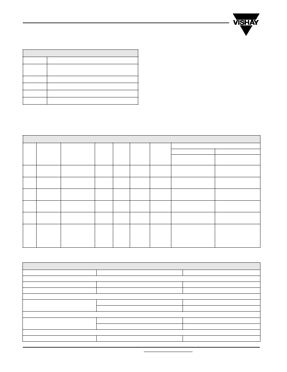
Table 1
RATED VOLTAGE MARKING CODE
U
R
(V)
6.3
10
16
25
40
63
Code letter
C
D
E
F
G
H
QUICK REFERENCE DATA
DESCRIPTION
VALUE
Nominal case sizes
(L
◊
W
◊
H in mm)
8.8
◊
3.7
◊
3.9 and
11.9
◊
3.7
◊
3.9
Rated capacitance range, C
R
0.47 to 22
µ
F
Tolerance on C
R
10 to +50% or
±
20%
Rated voltage range, U
R
6.3 to 63 V
Category temperature range
40 to +85∞C
Endurance test at 85
∞
C
1000 hours
Useful life at 85 ∞C
1500 hours
Useful life at 40 ∞C;
1.4
◊
l
R
applied
40000 hours
Shelf life at 0 V, 85 ∞C
500 hours
Resistance to soldering
heat test
immersion in solder:
10 s at 260 ∞C or 20 s at 215 ∞C
Based on sectional
specification
IEC 60384-18/CECC 32300
Climatic category IEC 60068
40/085/56
085 CS
longer
life
139 CLL
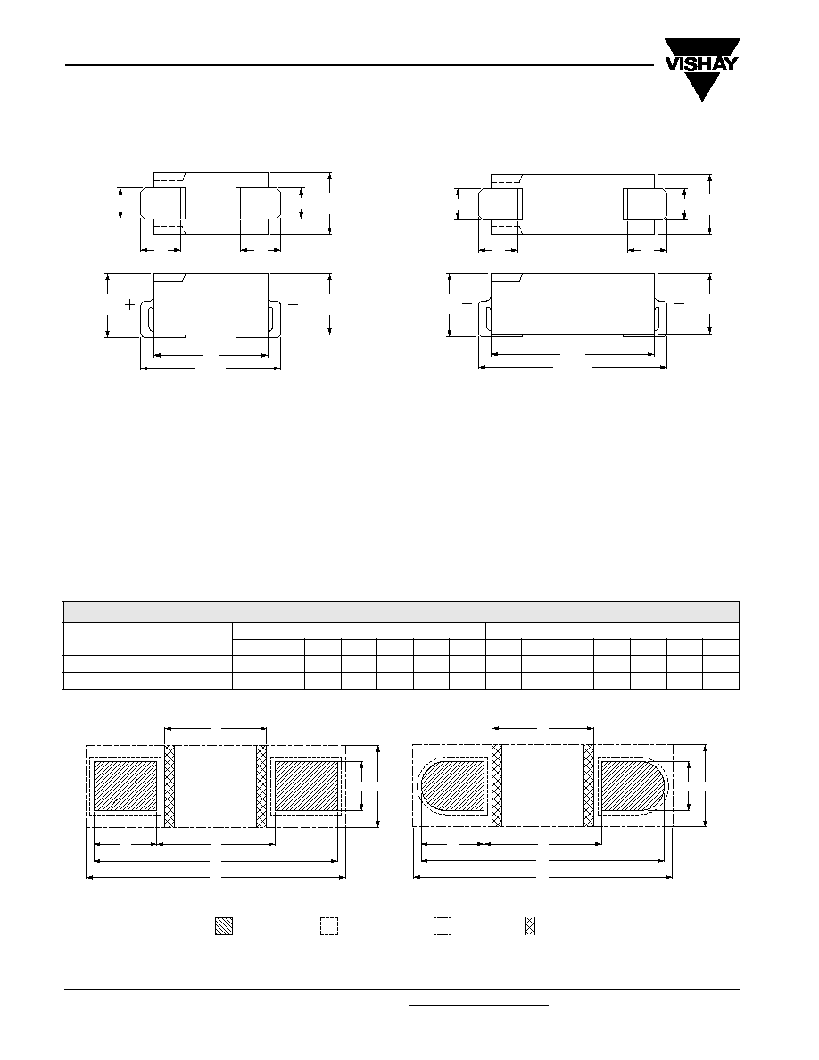
Fig.1 Component outlines
SELECTION CHART FOR C
R
, U
R
AND RELEVANT NOMINAL CASE SIZES
(L x W x H in mm)
C
R
(µF)
U
R
(V)
6.3
10
16
25
40
63
0.47
-
-
-
-
-
8.8
◊
3.7
◊
3.9
1.0
-
-
-
-
-
8.8
◊
3.7
◊
3.9
2.2
-
-
-
-
8.8
◊
3.7
◊
3.9
11.9
◊
3.7
◊
3.9
3.3
-
-
-
8.8
◊
3.7
◊
3.9
-
11.9
◊
3.7
◊
3.9
4.7
-
-
8.8
◊
3.7
◊
3.9
-
11.9
◊
3.7
◊
3.9
-
6.8
-
8.8
◊
3.7
◊
3.9
-
11.9
◊
3.7
◊
3.9
-
-
10
8.8
◊
3.7
◊
3.9
-
11.9
◊
3.7
◊
3.9
-
-
-
15
-
11.9
◊
3.7
◊
3.9
-
-
-
-
22
11.9
◊
3.7
◊
3.9
-
-
-
-
-
www.vishay.com
For technical questions contact: aluminumcaps1@vishay.com
Document Number: 28300
2
Revision: 22-Sep-03
085 CS
Vishay BCcomponents
Aluminum Capacitors
SMD (Chip) Standard
DIMENSIONS
in millimeters
7.5
9 max
2.7
max
2 max
3.9
max
4.1
max
2 max
3.9
max
2.7
max
Fig.2 Dimensional outlines.
a. Case size 8.8 ◊ 3.7 ◊ 3.9 mm.
10.8
12.2 max
2.7
max
2 max
3.9
max
4.1
max
2 max
3.9
max
2.7
max
a.
b.
b. Case size 11.9 x 3.7 x 3.9 mm.
PACKAGING
Tape on reel packaging: 2000 per reel.
Detailed tape dimensions see section `PACKAGING'.
MOUNTING
The capacitors are designed for automatic placement on
printed-circuit boards or hybrid circuits.
Optimum dimensions of soldering pads depend upon
soldering method, mounting accuracy, print lay-out and/or
adjacent components.
For recommended pad dimensions, refer to Fig. 3
and Table 2.
Table 2
RECOMMENDED SOLDERING PAD DIMENSIONS
in millimeters (placement accuracy ±0.25mm)
NOMINAL CASE SIZE
L
◊
◊
◊
◊
W
◊
◊
◊
◊
H
FOR REFLOW SOLDERING
FOR WAVE SOLDERING
A
B
C
D
E
F
G
A
B
C
D
E
F
G
8.8
◊
3.7
◊
3.9
9.7
3.5
2.9
2.5
3.0
10.1
4.4
13.5
4.1
4.7
3.7
2.9
14.0
8.4
11.9
◊
3.7
◊
3.9
12.9
6.5
2.9
2.5
6.0
13.3
4.4
16.8
7.4
4.7
3.7
6.1
17.3
8.4
solder land/
solder paste
pattern
solder resist
pattern
occupied
area
tracks or
dummy tracks
E
D
G
C
B
A
F
E
D
G
C
B
A
F
reflow soldering
wave soldering
Fig.3 Recommended pad dimensions for reflow and wave soldering.

Document Number: 28300
For technical questions contact: aluminumcaps1@vishay.com
www.vishay.com
Revision: 22-Sep-03
3
085 CS
Aluminum Capacitors
SMD (Chip) Standard
Vishay BCcomponents
b
a
d
+
+
++
c
flow-direction of solder
Fig.4 Minimum distances between 085 CS capacitors on a printed-circuit board for wave soldering.
For dimensions a, b, c and d, refer to Table 3 .
Flow direction of solder preferably onto side-walls or plus-side of the capacitors.
SOLDERING
Soldering conditions are defined by the curve, temperature
versus time. The temperature is that measured on the
soldering pad during processing.
For maximum conditions of different soldering methods see
Figs 5, 6 and 7.
Any temperature/time curve which does not exceed the
specified maximum curves may be applied.
AS A GENERAL PRINCIPLE, TEMPERATURE AND
DURATION SHALL BE THE
MINIMUM
NECESSARY
REQUIRED TO ENSURE GOOD SOLDERING
CONNECTIONS.
Table 3
MINIMUM DISTANCES BETWEEN
CAPACITORS
in millimeters
NOMINAL CASE
SIZE
L
◊
◊
◊
◊
W
◊
◊
◊
◊
H
CASE
CODE
a
min
b
min
c
min
d
min
8.8
◊
3.7
◊
3.9
1a
12
12
6.8
6.8
11.9
◊
3.7
◊
3.9
1
15
15
6.8
6.8
Table 4
CURING CONDITIONS FOR SMD-GLUE
MAX. T
amb
(
∞
∞
∞
∞
C)
MAX. EXPOSURE TIME
(minutes)
125
10
140
3
150
1
160
0.5
250
280
80
0
50
200
180
150
100
200
220
240
260
160
140
120
100
T
PAD
( C)
o
t (s)
Fig.5
Maximum temperature load
during infrared reflow soldering.
250
280
80
0
50
200
180
150
100
200
220
240
260
160
140
120
100
T
PAD
( C)
o
t (s)
Fig.6
Maximum temperature load during
vapour phase reflow soldering.
250
280
80
0
50
200
180
150
100
200
220
240
260
160
140
120
100
T
PAD
( C)
o
t (s)
Fig.7
Maximum temperature load during
(double-) wave soldering.
www.vishay.com
For technical questions contact: aluminumcaps1@vishay.com
Document Number: 28300
4
Revision: 22-Sep-03
085 CS
Vishay BCcomponents
Aluminum Capacitors
SMD (Chip) Standard
Note
1. Unless otherwise specified, all electrical values in Table 5 apply at
T
amb
= 20
∞
C, P = 86 to 106 kPa, RH = 45 to 75%
.
ORDERING EXAMPLE
Electrolytic capacitor 085 series
10 µF/16 V; -10/+50%
Nominal case size: 11.9 ◊ 3.7 ◊ 3.9 mm; Form BR
Catalog number: 2222 085 25109.
ELECTRICAL DATA
SYMBOL
DESCRIPTION
C
R
rated capacitance at 100 Hz
(tolerance -10 to +50% or ±20%)
I
R
rated RMS ripple current at 100 Hz, 85 ∞C
I
L5
max. leakage current after 5 minutes at U
R
Tan
max. dissipation factor at 100 Hz
Z
max. impedance at 10 kHz
Table 5
ELECTRICAL DATA AND ORDERING INFORMATION
U
R
(V)
C
R
100 Hz
(µ
µ
µ
µF)
NOMINAL
CASE SIZE
L ◊
◊
◊
◊ W ◊
◊
◊
◊ H
(mm)
I
R
100 Hz
85 ∞∞∞∞C
(mA)
I
L5
5 min
(µ
µ
µ
µA)
Tan
100 Hz
Z
10 kHz
(
)
CATALOG NUMBER 2222 085 .....
-
-
-
-10/+50%
±
±
±
±20%
BLISTER TAPE
ON REEL FORM BR
BLISTER TAPE
ON REEL FORM BR
6.3
10.0
8.8 ◊ 3.7 ◊ 3.9
11
3.1
0.30
20
23109
63109
22
11.9 ◊ 3.7 ◊ 3.9
20
3.3
0.30
9
23229
63229
10
6.8
8.8 ◊ 3.7 ◊ 3.9
10
3.1
0.25
24
24688
64688
15
11.9 ◊ 3.7 ◊ 3.9
18
3.3
0.25
11
24159
64159
16
4.7
8.8 ◊ 3.7 ◊ 3.9
9
3.2
0.20
26
25478
65478
10
11.9 ◊ 3.7 ◊ 3.9
16
3.3
0.20
12
25109
65109
25
3.3
8.8 ◊ 3.7 ◊ 3.9
8
3.2
0.18
27
26338
66338
6.8
11.9 ◊ 3.7 ◊ 3.9
14
3.3
0.18
13
26688
66688
40
2.2
8.8 ◊ 3.7 ◊ 3.9
7
3.2
0.16
32
27228
67228
4.7
11.9 ◊ 3.7 ◊ 3.9
13
3.4
0.16
15
27478
67478
63
0.47
8.8 ◊ 3.7 ◊ 3.9
4
3.1
0.10
120
28477
68477
1.0
8.8 ◊ 3.7 ◊ 3.9
6
3.1
0.12
55
28108
68108
2.2
11.9 ◊ 3.7 ◊ 3.9
11
3.3
0.14
25
28228
68228
3.3
11.9 ◊ 3.7 ◊ 3.9
13
3.4
0.14
17
28338
68338
ADDITIONAL ELECTRICAL DATA
PARAMETER
CONDITIONS
VALUE
Voltage
Surge voltage for short periods
U
s
1.15 ◊ U
R
Reverse voltage
U
rev
1 V
Current
Leakage current
after 1 minute at U
R
I
L1
0.02 C
R
◊ U
R
+ 3 µA
after 5 minutes at U
R
I
L5
0.002 C
R
◊ U
R
+ 3 µA
Inductance
Equivalent series inductance (ESL)
nominal case size 8.8 ◊ 3.7 ◊ 3.9 mm
typ. 11 nH
nominal case size 11.9 ◊ 3.7 ◊ 3.9 mm
typ. 13 nH
Resistance
Equivalent series resistance (ESR)
calculated from tan
max
and C
R
(see Table 5)
ESR = tan / 2fC
R

Document Number: 28300
For technical questions contact: aluminumcaps1@vishay.com
www.vishay.com
Revision: 22-Sep-03
5
085 CS
Aluminum Capacitors
SMD (Chip) Standard
Vishay BCcomponents
CAPACITANCE (C)
0
20
40
20
40
60
80
0.4
0.6
0.8
1.0
100
1.2
T amb ( C)
o
C
0
C
1
2
3
1
2
3
Fig.8 Typical multiplier of capacitance as a function of ambient
temperature.
Curve 1: 6.3 V.
Curve 2: 25 V.
Curve 3: 63 V.
C
0
= capacitance at 20 ∞C, 100 Hz.
10
4
10
3
10
2
10
f (Hz)
0.6
0.7
0.8
0.9
1.0
1.1
C
0
C
1
2
3
1
2
3
Fig.9 Typical multiplier of capacitance as a function of frequency.
Curve 1: 6.3 V.
Curve 2: 25 V.
Curve 3: 63 V.
C
0
= capacitance at 20 ∞C, 100 Hz.
T
amb
= 20 ∞C.
RIPPLE CURRENT AND USEFUL LIFE
3.3
3.2
3.0
2.8
2.6
2.4
2.2
2.0
1.8
1.6
1.4
1.2
1.0
0.8
0.5
0.0
3.1
40
50
60
70
80
90
100
T
amb
(∞C)
lifetime multiplier
(1)
70
50
4.0
6 .0
2.0
1.5
30
15
10
3.0
20
1.0
I
A
I
R
CCC205
Fig.10 Multiplier of useful life as a function of ambient temperature and ripple current load.
I
A
= actual ripple current at 100 Hz.
I
R
= rated ripple current at 100 Hz, 85 ∞C.
(1) Useful life at 85 ∞C and I
R
applied: 1500 hours.