www.vishay.com
161
1268
Vishay Foil Resistors
Document Number: 63059
Revision 06-Aug-02
TRIMMERS
VISHAY FOIL ∑ FRANCE +33.4.93.37.28.24 FAX: +33.4.93.37.27.31
∑ GERMANY +49.9287.710 FAX: +49 9287.70435
∑ ISRAEL +972.3.557.0945 FAX: +972.3.558.9121
∑ ITALY + 39.2.300.11919 FAX: +39.2.300.11999
∑ JAPAN +81.42.729.0661 FAX: +81.42.729.3400
∑ SINGAPORE +65.788.6668 FAX: +65.788.0988
∑ SWEDEN +46.8.594.70590 FAX: +46.8.594.70581
∑ UK +44 191 514 8237 FAX: +44 1953 457 722
∑ USA +1 610 407-4800 FAX: +1 610 640-9081
NOTES:
1. Maximum is 1.0% A.Q.L. standard for all specifications except TCR. (For TCR information see notes 2 and 3). "Typical" is
a designers reference which represents that 85% of the lots supplied, over a long period of time, will be at least the figure
stated or better.
2. Maximum TCR applies to the 3
(sigma) limit or 99.73% of a production lot. (Measured end-to-end with wiper off the element.)
3. Measurements of TCR through the wiper are influenced more by setting stability and the percentage of the total resistance
in use (at the wiper) than by fundamental resistance change due to temperature alone. The parameter shown is a 2
distribution typifying the behavior of the device when used with 40% or more of the total resistance in use.
4. Derated linearly from full power @ + 85
∞C to zero (0) watts @ + 150∞C. See Figure 2, next page.
5. Independent of resistance value 3 ohms maximum available on special request.
Special Available Options:
Special marking
Burn-in and screening operations
FEATURES
∑ Temperature Coefficient of Resistance (TCR):
± 20ppm/∞C Max
2
. (≠ 55
∞C to + 150∞C Ref. @ 25∞C);
Through the wiper
3
;
± 50ppm/∞C
∑ Load Life Stability: 0.1% Typical
R, 1.0% Maximum
R under Full Rated Power @ + 85∞C for 1000 Hours
∑ Settability: 0.1%
∑ Setting Stability: 0.1% Typical
1
; 0.5% Maximum
1
,
SS
∑ Power Rating
4
: 0.25 watts @ + 85
∞C
∑ Resistance Range: 20
to 5K
∑ Resistance Tolerance:
± 10%
*See Figure 1, next page.
ADDITIONAL SPECIFICATIONS:
∑ Contact Resistance Variation ≠ CRV (noise): 10 ohms Maximum
5
∑ Hop-off: 0.25% Typical; 1.0% Maximum
∑ Operating Temperature Range: ≠ 55
∞C to + 150∞C
∑ Adjustment Turns: 21
± 2
∑ Mechanical Stops: Wiper Idles ≠ No Discontinuity
MODEL NO.
TERMINATION
RESISTANCE
TOLERANCE
STYLE
VALUE
1268
W
100R
10%
AVERAGE
STANDARD RESISTANCE VALUES
STANDARD
POWER RATING @ NO. OF
MODEL
TERMINATION STYLE
WEIGHT (g)
(in
)
TOLERANCES
+ 85
∞
C AMBIENT
TURNS
1268
W-Edge Mount, Top Adjust
20, 50, 100,
0.4
200, 500, 1K
± 10%
0.25W
21
± 2
X-Edge Mount, Side Adjust
2K, 5K
Bulk Metal
Æ
Foil Technology
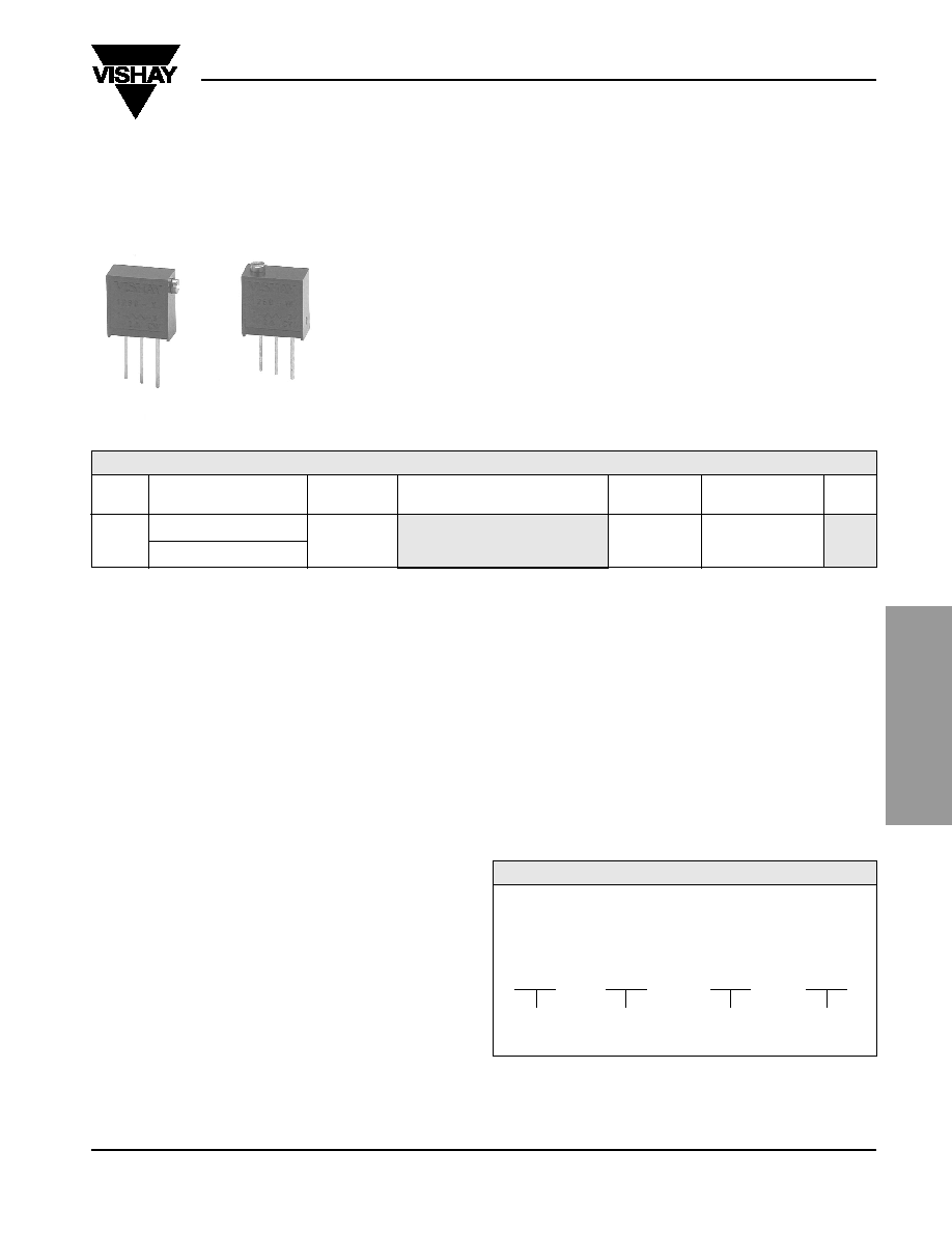
Precision Trimming Potentiometers
3/8 Inch Square, RJ24 Style - Industrial Trimmer
TABLE 1 - MODEL SELECTION *
Please specify Vishay Model 1268 Precision Trimming
Potentiometers as follows:
Example:
TABLE 2 - ORDERING INFORMATION - 1268 SERIES PARTS
See Table 1 for details. See Figure 1, next page for Standard Marking.
Product may not
be to scale

Document Number: 63059
Revision 06-Aug-02
www.vishay.com
162
1268
Vishay Foil Resistors
TRIMMERS
VISHAY FOIL ∑ FRANCE +33.4.93.37.28.24 FAX: +33.4.93.37.27.31
∑ GERMANY +49.9287.710 FAX: +49 9287.70435
∑ ISRAEL +972.3.557.0945 FAX: +972.3.558.9121
∑ ITALY + 39.2.300.11919 FAX: +39.2.300.11999
∑ JAPAN +81.42.729.0661 FAX: +81.42.729.3400
∑ SINGAPORE +65.788.6668 FAX: +65.788.0988
∑ SWEDEN +46.8.594.70590 FAX: +46.8.594.70581
∑ UK +44 191 514 8237 FAX: +44 1953 457 722
∑ USA +1 610 407-4800 FAX: +1 610 640-9081
1268X
STANDARD MARKING
Model No.
Date Code
Resistance Value
Tolerance
NOTES
Adjustment screw 0.090 Inches
(2.30mm) diameter with 0.020
Inches (0.51mm) x 0.031 Inches
(0.80mm) slot. Model 1268
has solder plated copper
terminal pins. 0.024 Inches
(0.61mm) diameter, 0.300 Inches
(7.62mm) length minimum.
1268W
0.024
±0.006" (0.61 ±0.15mm) DIA
3 PINS
VISHAY
2
3
1
CW
0.420" (10.67mm) MAX
0.080" (2.03mm) MAX
0.300" (7.62mm) MIN
0.015" (0.38mm) MIN
0.187
±0.020"
(4.75
±0.51mm)
0.100
±0.005"
(2.54
±0.13mm)
±0.010" (±0.25mm)
C
0.090
±0.005"
(2.29
±0.13mm) DIA
0.170
±0.025"
(4.32
±0.64mm)
0.075
±0.010"
(1.91
±0.25mm)
0.375
±0.015"
(9.53
±0.38mm)
0.081
±0.010"
(2.08
±0.25mm)
0.024
±0.006" (0.61 ±0.15mm) DIA
3 PINS
0.081
±0.010" (2.08 ±0.25mm)
VISHAY
2
3
1
CW
0.420" (10.67mm) MAX
0.080" (2.03mm) MAX
0.300" (7.62mm) MIN
0.015" (0.38mm) MIN
0.187
±0.020"
(4.75
±0.51mm)
0.100
±0.005"
(2.54
±0.13mm)
±0.010" (±0.25mm) C
0.090
±0.005"
(2.29
±0.13mm) DIA
0.170
±0.025"
(4.32
±0.64mm)
0.075
±0.010"
(1.91
±0.25mm)
0.375
±0.015"
(9.53
±0.38mm)
FIGURE 2 - POWER DERATING CURVE
-75
-50
-25
0
+25
+50
+75 +100 +125 +150 +175
Ambient Temperature
∞C
+85
∞C
+100
+75
+50
+25
0
Percent of Rated Power
FIGURE 1 - SCHEMATIC AND DIMENSIONS in inches (millimeters)
Bulk Metal
Æ
Foil Technology
Precision Trimming Potentiometers
MAXIMUM
MAXIMUM
MINIMUM
MINIMUM
DIAMETER
DIAMETER
MAXIMUM
MAXIMUM
MINIMUM
MINIMUM