 | –≠–ª–µ–∫—Ç—Ä–æ–Ω–Ω—ã–π –∫–æ–º–ø–æ–Ω–µ–Ω—Ç: 140CLH | –°–∫–∞—á–∞—Ç—å:  PDF PDF  ZIP ZIP |
140 CLH
Vishay BCcomponents
Aluminum Capacitors
SMD (Chip), High Temperature
Document Number: 28303
For technical questions contact: aluminumcaps1@vishay.com
www.vishay.com
Revision: 23-Jun-05
1
FEATURES
∑ Polarized aluminum electrolytic capacitors,
non-solid electrolyte, self healing
∑ SMD-version with base plate, reflow solderable
∑ High temperature, 1500 hours at 125 ∞C
∑ High capacitance values
∑ Charge and discharge proof, no peak current limitation
∑ Lead (Pb)-free terminations available
∑ ATTENTION: for maximum safe soldering conditions refer
to fig.4
APPLICATIONS
∑ SMD technology, for high mounting density
∑ Industrial and professional applications
∑ Automotive, general industrial
∑ Smoothing, filtering, buffering.
MARKING
∑ Rated capacitance (in F).
∑ Rated voltage (in V).
∑ Date code, in accordance with IEC 60062.
∑ Black mark or `-' sign indicating the cathode
(the anode is identified by bevelled edges).
∑ Code indicating group number (H).
PACKAGING
Supplied in blister tape on reel.
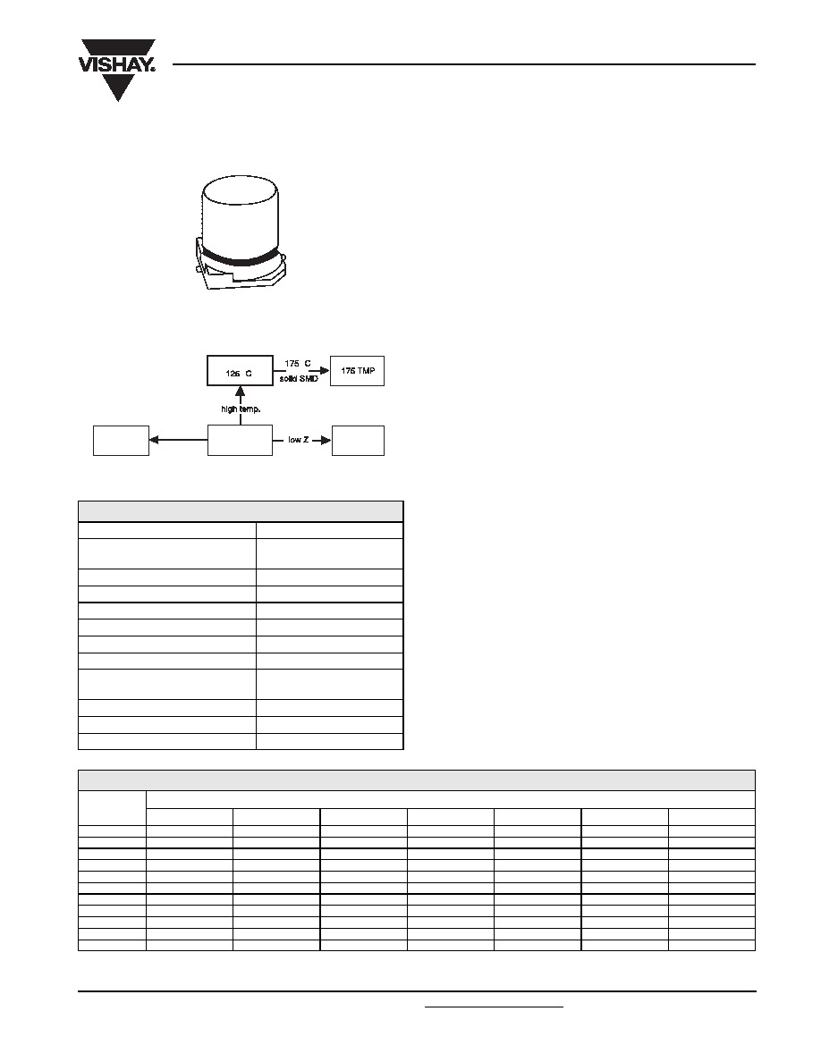
Fig.1 Component outline.
∞
∞
153 CRV
Lead (Pb)-free
153 CLV
140 CLH
150 CLZ
QUICK REFERENCE DATA
DESCRIPTION
VALUE
Nominal case sizes
(L
◊ W ◊ H in mm)
8
◊ 8 ◊ 10
to 10
◊ 10 ◊ 14
Rated capacitance range, C
R
10 to 680
F
Tolerance on C
R
±20%
Rated voltage range, U
R
6.3 to 63 V
Category temperature range
-55 to +125 ∞C
Endurance test at 125
∞C
1000 hours
Useful life at 125
∞C
1500 hours
Useful life at 40
∞C;
1.8
◊ l
R
applied
150000 hours
Shelf life at 0 V, 125
∞C
1000 hours
Based on sectional specification
IEC 60384-18/CECC 32300
Climatic category IEC 60068
55/125/56
SELECTION CHART FOR C
R
, U
R
AND RELEVANT NOMINAL CASE SIZES (L x W x H in mm)
C
R
(
F)
U
R
(V)
6.3
10
16
25
35
50
63
10
-
-
-
-
-
-
8
◊ 8 ◊ 10
22
-
-
-
-
-
-
8
◊ 8 ◊ 10
33
-
-
-
-
-
-
8
◊ 8 ◊ 10
47
-
-
-
-
-
8
◊ 8 ◊ 10
10
◊ 10 ◊ 10
68
-
-
-
-
8
◊ 8 ◊ 10
10
◊ 10 ◊ 10
10
◊ 10 ◊ 14
100
-
-
-
8
◊ 8 ◊ 10
10
◊ 10 ◊ 10
10
◊ 10 ◊ 14
-
150
-
-
8
◊ 8 ◊ 10
-
10
◊ 10 ◊ 14
-
-
220
-
8
◊ 8 ◊ 10
-
10
◊ 10 ◊ 10
-
-
-
330
8
◊ 8 ◊ 10
10
◊ 10 ◊ 10
10
◊ 10 ◊ 14
-
-
-
-
470
10
◊ 10 ◊ 10
10
◊ 10 ◊ 14
-
-
-
-
-
680
10
◊ 10 ◊ 14
-
-
-
-
-
-
140 CLH
Vishay BCcomponents
Aluminum Capacitors
SMD (Chip), High Temperature
www.vishay.com
For technical questions contact: aluminumcaps1@vishay.com
Document Number: 28303
2
Revision: 23-Jun-05
Table 1
Table 2
Note
1. Detailed tape dimensions see section "PACKAGING".
DIMENSIONS in millimeters AND MASS
NOMINAL
CASE SIZE
L
◊ W ◊ H
CASE
CODE
L
max
W
max
H
max
D
B
max
S
L
1 max
MASS
(g)
8
◊ 8 ◊ 10
0810
8.5
8.5
10.5
8.0
1.0
3.1
9.9
1.0
10
◊10 ◊ 10
1010
10.5
10.5
10.5
10.0
1.0
4.5
11.8
1.3
10
◊ 10 ◊ 14
1014
10.5
10.5
14.3
10.0
1.0
4.5
11.8
1.5
TAPE AND REEL DIMENSIONS in millimeters, PACKAGING QUANTITIES
NOMINAL
CASE SIZE
L
◊ W ◊ H
CASE
CODE
PITCH
P
1
TAPE WIDTH
W
TAPE THICKNESS
T
2
REEL
DIA.
PACKAGING
QUANTITY
PER REEL
8
◊ 8 ◊ 10
0810
16
24
11.3
380
500
10
◊10 ◊ 10
1010
16
24
11.3
380
500
10
◊ 10 ◊ 14
1014
16
24
14.8
330
250
MOUNTING
The capacitors are designed for automatic placement on to
printed-circuit boards.
Optimum dimensions of soldering pads depend amongst
others on soldering method, mounting accuracy, print lay-out
and/or adjacent components.
For recommended soldering pad dimensions, refer to
Fig.3
and Table 3.
SOLDERING
Soldering conditions are defined by the curve, temperature
versus time, where the temperature is that measured on the
soldering pad during processing.
For maximum conditions refer to
Fig.4
.
Any temperature versus time curve which does not exceed
the specified maximum curves may be applied.
AS A GENERAL PRINCIPLE, TEMPERATURE AND
DURATION SHALL BE THE MINIMUM NECESSARY
REQUIRED TO ENSURE GOOD SOLDERING
CONNECTIONS. HOWEVER, THE SPECIFIED MAXIMUM
CURVES SHOULD NEVER BE EXCEEDED.
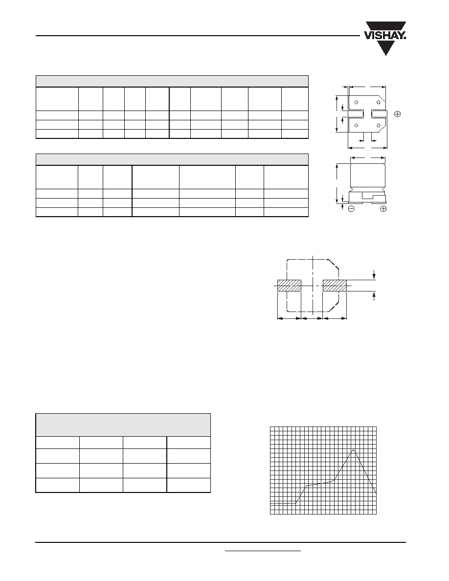
c
a
a
b
Fig.3 Recommended soldering pad dimensions.
Table 3
RECOMMENDED SOLDERING PAD
DIMENSIONS in millimeters
CASE CODE
a
b
c
0810
3.5
2.5
3.0
1010
4.3
2.5
4.0
1014
4.3
2.5
4.0
Fig.4 Maximum temperature load during infrared reflow
soldering measured on the soldering pad.
250
280
80
0
50
200
180
150
100
200
220
240
260
160
140
120
100
T
PAD
( C)
o
t (s)
H
W B
0.3
max.
0.4
±0.2
D
L1
S
L

140 CLH
Aluminum Capacitors
SMD (Chip), High Temperature
Vishay BCcomponents
Document Number: 28303
For technical questions contact: aluminumcaps1@vishay.com
www.vishay.com
Revision: 23-Jun-05
3
Note
1. Unless otherwise specified, all electrical values in Table 4 apply
at Tamb = 20 ◊C, P = 86 to 106 kPa, RH = 45 to 75%.
ORDERING EXAMPLE*
Electrolytic capacitor 140 CLH series
100
F/50 V; ±20%
Nominal case size:
10
◊ 10 ◊ 14 mm; taped on reel
Catalog number: 2222 140 95102.
*Note: For ordering lead (Pb)-free parts, please contact your
Vishay sales agent.
ELECTRICAL DATA
SYMBOL
DESCRIPTION
C
R
rated capacitance at 100 Hz, tolerance ±20%
I
R
rated RMS ripple current at 100 kHz, 125 ∞C
I
L2
max. leakage current after 2 minutes at U
R
Tan
max. dissipation factor at 100 Hz
Z
max. impedance at 100 kHz
Table 4
ELECTRICAL DATA AND ORDERING INFORMATION
U
R
(V)
C
R
(
F)
NOMINAL
CASE SIZE
L
◊ W ◊ H
(mm)
I
R
100 kHz
125
∞C
(mA)
I
L2
2 min
(
A)
Tan
Z
100 kHz
+20
∞C
(
)
CATALOG NUMBER
2222 140 .....
6.3
330
8
◊ 8 ◊ 10
180
21
0.30
0.65
95303
470
10
◊ 10 ◊ 10
300
30
0.30
0.17
95301
680
10
◊ 10 ◊ 14
430
43
0.30
0.12
95302
10
220
8
◊ 8 ◊ 10
180
22
0.26
0.65
95403
330
10
◊ 10 ◊ 10
300
33
0.26
0.17
95401
470
10
◊ 10 ◊ 14
430
47
0.26
0.12
95402
16
150
8
◊ 8 ◊ 10
180
24
0.22
0.65
95502
330
10
◊ 10 ◊ 14
430
53
0.22
0.12
95501
25
100
8
◊ 8 ◊ 10
180
25
0.18
0.65
95602
220
10
◊ 10 ◊ 10
300
55
0.18
0.19
95601
35
68
8
◊ 8 ◊ 10
180
24
0.14
0.65
95003
100
10
◊ 10 ◊ 10
255
35
0.14
0.40
95001
150
10
◊ 10 ◊ 14
317
53
0.14
0.30
95002
50
47
8
◊ 8 ◊ 10
145
24
0.12
1.00
95103
68
10
◊ 10 ◊ 10
205
34
0.12
0.56
95101
100
10
◊ 10 ◊ 14
255
50
0.12
0.42
95102
63
10
8
◊ 8 ◊ 10
145
6.3
0.12
1.00
95805
22
8
◊ 8 ◊ 10
145
14
0.12
1.00
95803
33
8
◊ 8 ◊ 10
145
21
0.12
1.00
95804
47
10
◊ 10 ◊ 10
205
30
0.12
0.56
95801
68
10
◊ 10 ◊ 14
255
43
0.12
0.42
95802
ADDITIONAL ELECTRICAL DATA
PARAMETER
CONDITIONS
VALUE
Voltage
Surge voltage for short periods
IEC 60384-18, subclause 4.14
U
s
1.15 ◊ U
R
Reverse voltage for short periods
IEC 60384-18, subclause 4.16
U
rev
0.5 V
Current
Leakage current
after 2 minutes at U
R
I
L2
0.01 ◊ C
R
◊ U
R
Inductance
Equivalent series inductance (ESL)
typ. 16 nH
Resistance
Equivalent series resistance (ESR) at 100 Hz
calculated from tan
max
and C
R
(see Table 4)
ESR = tan
/ 2fC
R
140 CLH
Vishay BCcomponents
Aluminum Capacitors
SMD (Chip), High Temperature
www.vishay.com
For technical questions contact: aluminumcaps1@vishay.com
Document Number: 28303
4
Revision: 23-Jun-05
CAPACITANCE (C)
DISSIPATION FACTOR (tan
)
-60
0
20
-40
-20
40
60
80
T
amb
(
∞C)
0.8
0.9
1.0
1.1
100
140
120
1.2
C
C
0
1
2
2
1
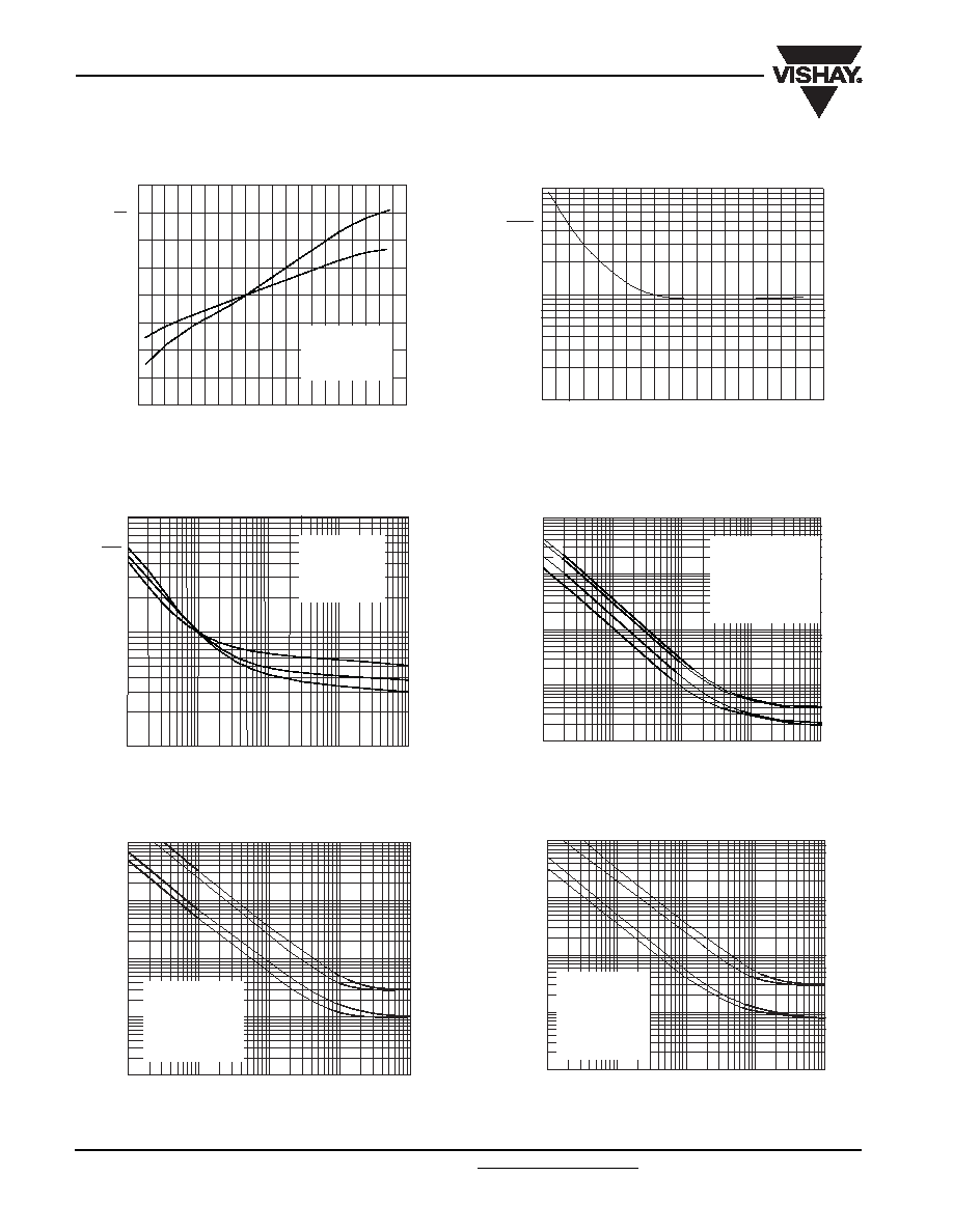
Fig.5 Typical multiplier of capacitance as a function
of ambient temperature.
Curve 1: 6.3 V.
Curve 2: 63 V.
C
0
= capacitance at 20
∞C, 100 Hz.
140
120
100
80
60
40
20
0
-20
-40
-60
10
1
0.1
Tan
Tan
0
T
amb
(
∞C)
Fig.6 Multiplier of dissipation factor (tan
) as a function of
ambient temperature.
tan
0 = typical tan at 20 ∞C, 100 Hz.
EQUIVALENT SERIES RESISTANCE (ESR)
IMPEDANCE (Z)
0.1
10
10
4
10
3
10
2
10
5
1
10
f (Hz)
2
3
3
1
2
1
ESR
ESR
0
Fig.7 Typical multiplier of ESR as a function of frequency.
Curve 1: 6.3 V.
Curve 2: 35 V.
Curve 3: 63 V.
ESR
0
= typical ESR at 20
∞C, 100 Hz.
T
amb
= 20
∞C.
10
10
2
10
3
10
4
10
5
f (Hz)
Z
( )
10
-1
1
10
10
2
10
3
1
2
3
4
Fig.8 Typical impedance as a function of frequency.
Case code 0810
Curve 1: 10 V.
Curve 2: 25 V.
Curve 3: 50 V.
Curve 4: 63 V.
T
amb
= 20
∞C.
10
10
2
10
3
10
4
10
5
f (Hz)
Z
( )
0.01
0.1
1
10
10
2
1
2
3
4
Fig.9 Typical impedance as a function of frequency.
Case code 1010
Curve 1: 10 V.
Curve 2: 25 V.
Curve 3: 50 V.
Curve 4: 63 V.
T
amb
= 20
∞C.
10
10
2
10
3
10
4
10
5
f (Hz)
Z
( )
0.01
0.1
1
10
10
2
1
2
3
4
Fig.10 Typical impedance as a function of frequency.
Case code 1014
Curve 1: 10 V.
Curve 2: 16 V.
Curve 3: 50 V.
Curve 4: 63 V.
T
amb
= 20
∞C.
140 CLH
Aluminum Capacitors
SMD (Chip), High Temperature
Vishay BCcomponents
Document Number: 28303
For technical questions contact: aluminumcaps1@vishay.com
www.vishay.com
Revision: 23-Jun-05
5
Table 5
MULTIPLIER OF RIPPLE CURRENT (I
R
) AS A FUNCTION OF FREQUENCY
FREQUENCY
(Hz)
I
R
MULTIPLIER
U
R
= 6.3 to 25 V
U
R
= 35 and 50 V
U
R
= 63 V
50
0.60
0.45
0.40
100
0.70
0.60
0.55
300
0.80
0.75
0.70
1000
0.85
0.85
0.85
3000
0.90
0.90
0.90
10000
0.95
0.95
0.95
30000
0.97
0.97
0.97
100000
1.00
1.00
1.00
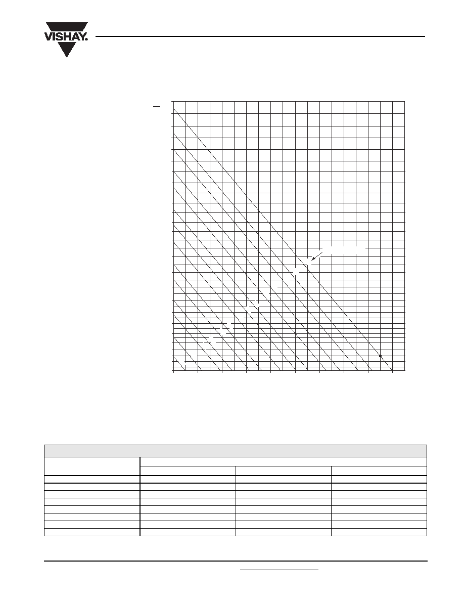
RIPPLE CURRENT AND USEFUL LIFE
3.8
3.7
3.6
3.5
3.4
3.3
3.2
3.0
2.8
2.6
2.4
2.2
2.0
1.8
1.6
1.4
1.2
1.0
0.8
0.5
0.0
3.1
40
50
60
70
80
90
100
110
120
130
3.9
4.0
4.1
4.2
4.3
I A
R
I
lifetime multiplier
(1)
6.0
4.0
2.0
1.5
1.0
3.0
400
100
60
20
30
12
8.0
200
Tamb( C)
o
MBC242
Fig.11 Multiplier of useful life as a function of ambient temperature and ripple current load.
IA = actual ripple current at 100 kHz.
IR = rated ripple current at
100 kHz,125
∞C.
140 CLH
Vishay BCcomponents
Aluminum Capacitors
SMD (Chip), High Temperature
www.vishay.com
For technical questions contact: aluminumcaps1@vishay.com
Document Number: 28303
6
Revision: 23-Jun-05
Table 6
TEST PROCEDURES AND REQUIREMENTS
TEST
PROCEDURE
(quick reference)
REQUIREMENTS
NAME OF TEST
REFERENCE
Mounting
IEC 60384-18,
subclause 4.3
shall be performed prior to tests mentioned below;
reflow soldering;
for maximum temperature load
refer to chapter "Mounting"
C/C: ±5%
tan
spec. limit
I
L2
spec. limit
Endurance
IEC 60384-18/
CECC 32 300,
subclause 4.15
T
amb
= 125
∞C; U
R
applied;
1000 hours
U
R
= 6.3 V;
C/C: ±25%
U
R
10 V; C/C: ±20%
tan
2 ◊ spec. limit
I
L2
spec. limit
Useful life
CECC 30301,
subclause 1.8.1
T
amb
= 125
∞C; U
R
and I
R
applied;
1 500 hours
C/C: ±50%
tan
3 ◊ spec. limit
I
L2
spec. limit
no short or open circuit
total failure percentage:
1%
Shelf life
(storage at high
temperature)
IEC 60384-18/
CECC 32 300,
subclause 4.17
T
amb
= 125
∞C; no voltage applied;
1000 hours
after test: U
R
to be applied for 30 minutes,
24 to 48 hours before measurement
for requirements
see `Endurance test' above
Reverse voltage
IEC 60384-18/
CECC 32 300,
subclause 4.16
T
amb
= 125
∞C:
125 hours at U =
-0.5 V,
followed by 125 hours at U
R
C/C: ±15%
tan
1.5 ◊ spec. limit
I
L2
spec. limit