PTC Thermistors For Degaussing,
Dual, Mono And Double Mono Cased
2322 662 96...
Vishay BCcomponents
www.vishay.com
For technical questions contact: nlr.europe@vishay.com
Document Number: 29077
184
Revision: 10-Oct-03
FEATURES
∑
Residual currents as low as 2 mA (p-p), ideal for
high-resolution displays
∑
Long decay time
∑
Stable performance over a long time (
>
20000 operations)
∑
Self-extinguishing white plastic case (
"UL 94.V.0"
)
∑
Design-in support available.
APPLICATIONS
∑
Colour televisions
∑
Colour monitors.
DESCRIPTION
For good picture definition, colour televisions and monitors
must be degaussed by a strong alternating magnetic field
which gradually and symmetrically decays to a small value of
residual current. This can be achieved by connecting a PTC
thermistor in the degaussing circuit.
The new generation of flat-screen, high-definition colour
televisions and monitors require an excellent picture quality
with high colour purity. This can only be achieved by a dual
PTC device housing two PTC thermistors in intimate thermal
contact, one being used to heat the other and so further
reduce the residual current.
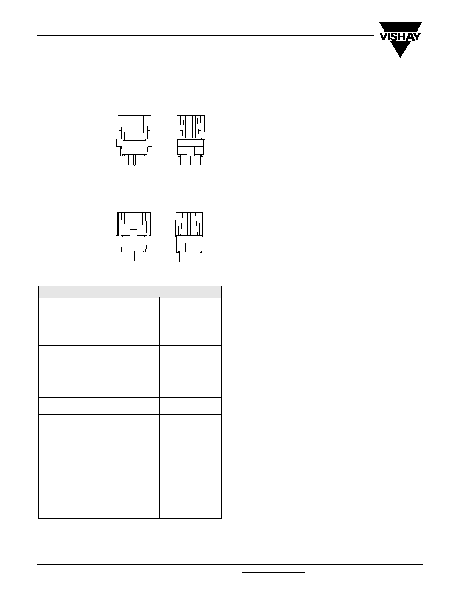
MBB633
CCB442
a. Dual or double mono
PTC degaussing.
b. Mono PTC
degaussing.
QUICK REFERENCE DATA
PARAMETER
VALUE
UNIT
Resistance of degaussing PTC (R
s
) at
25
∞
C
3 to 30
Standard tolerance on resistance of
degaussing PTC (R
s
) at 25
∞
C
20 and 25
%
Resistance of heater PTC (R
p
) at 25
∞
C
3000
Standard tolerance on resistance of
heater PTC (R
p
) at 25
∞
C
75
%
Maximum AC voltage (RMS value)
145 to 276
V
Minimum inrush current (peak-to-peak
value)
10 to 30
A
Temperature range (at maximum voltage)
0 to 60
∞
C
Available pitch:
4e/1e
10.16 to 2.54
mm
4e/2e
10.16 to 5.08
mm
Standard pin length
4.2
mm
Detailed specifications based on
CECC 44000/
IEC 60738

2322 662 96...
PTC Thermistors For Degaussing,
Dual, Mono And Double Mono Cased
Vishay BCcomponents
Document Number: 29077
For technical questions contact: nlr.europe@vishay.com
www.vishay.com
Revision: 10-Oct-03
185
DUAL RANGE
ELECTRICAL DATA AND ORDERING INFORMATION
MINIMUM
PEAK-TO-PEAK
(2)(6)
INRUSH CURRENT
(A)
MAXIMUM
PEAK-TO-PEAK
(2)
RESIDUAL CURRENT
(mA)
R
25
(3)
(
)
R
coil
(4)(6)
(
)
TYPICAL DECAY
PERFORMANCE
TYPE
(8)
CATALOG NUMBER
(9)
2322 662 .....
after
5 s
after
30 s
after
180 s
R
s
±
±
±
±
%
MIN.
TYP.
DECAY
TIME
(5)(6)
(ms)
ALPHA
MAX.
(6)
(%)
4e/1e pitch
4e/2e pitch
U
R
= 220 to 240 V
RMS
(U
max
= 276 V
RMS
)
11
50
5
2
30
25
17
25
60
36
-
96209
96309
14
50
5
2
26
25
14
17
40
43
-
96211
96311
16
80
8
4
22
25
14
17
40
44
-
96216
96316
16
80
8
2
22
25
10
17
65
33
LD
96616
96716
20
80
8
2
18
25
10
13
50
38
-
96624
96724
18
80
15
2
18
25
10
17
75
29
LD
96626
96726
25
80
10
4
14
25
10
10
40
45
-
96602
96702
25
80
10
4
14
25
10
10
45
40
LD
96642
96742
21
80
10
5
12
20
10
17
70
36
LT
96606
96706
21
100
20
5
12
20
10
17
80
30
LD/LT
96646
96746
20
100
40
5
9
20
13
20
95
33
LT
96608
96708
20
100
25
10
9
20
13
20
115
26
LD/LT
96648
96748
21
100
40
10
7
20
20
20
110
33
LD/LT
-
96709
U
R
= 100 to 120 V
RMS
(U
max
= 145 V
RMS
)
19
200
20
10
7
20
5
7
80
31
LT
96213
96313
27
200
50
14
5
30/15
5
6
85
30
-
96605
96705
30
200
20
10
5
20
4
5
85
31
LD/LT
96645
96745
30
200
20
10
3
30/15
4
6
115
29
LD
96643
96743
MONO CASED RANGE
ELECTRICAL DATA AND ORDERING INFORMATION
Notes
1. Electrical data and catalog numbers. The shading indicates preferred types.
2.
All peak-to-peak currents are measured at typical resistance of the coil, at 50 Hz (AC), at 25∫C and at 220 Vrms for the 276V types, and 110Vrms for the 145V types.
3. Lower tolerances on resistance of degaussing PTC are available on request.
4. Lower minimum coil resistance is available on request.
5. Decay time is the time from the moment of maximum peak current until the half of the maximum peak inrush current.
6. Alpha maximum is the maximum decrease in current expressed in percent between two successive peaks.
7. Inrush currents and decay times at other voltage coil combinations can be derived from Figures 7 to 13, see section
`Introduction, PTC thermistors for degaussing".
8. LT = low tolerance; LD = long decay.
9. Smallest packaging quantity (SPQ) = 600 units.
MINIMUM
PEAK-TO-PEAK
(2)
INRUSH
CURRENT
(A)
MAXIMUM
PEAK-TO-PEAK
(2)
RESIDUAL CURRENT
(mA)
R
25
(3)
(
)
R
coil
(4)(7)
(
)
TYPICAL DECAY
PERFORMANCE
TYPE
(8)
CATALOG NUMBER
(9)
2322 662 .....
after
5 s
after
30 s
after
180 s
R
s
±
±
±
±
%
MIN.
TYP.
DECAY
TIME
(5)(7)
(ms)
ALPHA
MAX.
(6)
(%)
4e pitch
U
R
= 220 to 240 V
RMS
(U
max
= 276 V
RMS
)
11
100
40
20
30
25
17
25
75
30
-
96281
12
50
30
20
26
25
14
25
90
30
-
96688
16
80
40
20
22
25
14
17
40
44
-
96286
20
100
50
25
18
25
10
13
50
38
-
96682
25
200
50
30
14
25
10
10
40
45
-
96683
25
200
80
30
14
25
10
10
45
40
LD
96692
21
200
80
30
12
20
10
17
70
36
-
96684
21
200
80
30
12
20
10
17
80
30
LD
96696
20
100
50
30
9
20
13
20
95
33
LT
96687
20
200
50
25
9
20
13
20
115
26
LD/LT
96698
21
100
50
30
7
20
20
20
110
33
LD/LT
96681
U
R
= 100 to 120 V
RMS
(U
max
= 145 V
RMS
)
19
200
70
40
7
20
5
7
80
31
-
96285
27
200
70
40
5
30/1
5
6
85
30
-
96686
30
200
70
40
5
20
4
5
85
31
LD
96695
30
200
70
40
3
30/1
4
6
115
29
LD
96693

2322 662 96...
Vishay BCcomponents
PTC Thermistors For Degaussing,
Dual, Mono And Double Mono Cased
www.vishay.com
For technical questions contact: nlr.europe@vishay.com
Document Number: 29077
186
Revision: 10-Oct-03
DOUBLE MONO CASED RANGE
ELECTRICAL DATA AND ORDERING INFORMATION
Notes
1. All peak-to-peak currents are measured at typical resistance of the coil, at 50 Hz (AC), at 25∫C and at 220 Vrms for the 276V types, and 110Vrms for the 145V types
.
2. Lower minimum coil resistance is available on request.
3. The indicated resistance value is the parallel combination of two degaussing PTCs.
4. Decay time is the time from the moment of maximum peak current until the half of the maximum peak inrush current.
5. Alpha maximum is the maximum decrease in current expressed in percent between two successive peaks.
6. Inrush currents and decay times at other voltage coil combinations can be derived from Figures 7 to 13 in the section,
"Introduction, PTC thermistors for degaussing".
7. LT = low tolerance; LD = long decay.
8.
Smallest packaging quantity (SPQ) = 600 units.
MINIMUM
PEAK-TO-PEAK
(1)
INRUSH
CURRENT
(A)
MAXIMUM
PEAK-TO-PEAK
(1)
RESIDUAL CURRENT
(mA)
R
25
(3)
(
)
R
coil
(2)(6)
(
)
TYPICAL DECAY
PERFORMANCE
TYPE
(7)
CATALOG NUMBER
(8)
2322 662 .....
after
5 s
after
30 s
after
180 s
R
s
±
±
±
±
%
MIN.
TYP.
DECAY
TIME
(4)(6)
(ms)
ALPHA
MAX.
(5)
(%)
4e/2e pitch
U
R
= 220 to 240 V
RMS
(U
max
= 276 V
rms
)
33
200
35
25
9.0 (18
◊
2)
25
7
10
80
31
LD
96754
34
200
35
25
7.0 (14
◊
2)
25
7
10
80
31
LD
96752
36
200
40
30
6.0 (12
◊
2)
20
7
10
85
31
LD/LT
96756
33
200
45
35
4.5 (9
◊
2)
20
10
13
130
27
LD/LT
96758
35
200
50
40
3.5 (7
◊
2)
20
13
13
135
27
LD/LT
96759
U
R
= 100 to 120 V
RMS
(U
max
= 145 V
rms
)
27
250
80
45
3.5 (7
◊
2)
20
3
7
255
16
LD/LT
96757
34
250
80
45
2.5 (5
◊
2)
20
3
6
200
19
LD/LT
96755
39
250
80
45
1.5 (3
◊
2)
20
4
6
250
21
LD/LT
96753
INRUSH CURRENT
APPLICATION SPECIFIC DATA
The data shown in the above tables is obtained from measurements at reference parameters. If these parameters do not
correspond to the application parameters required, refer to Figures 7 to 13 in the
"Introduction, PTC thermistors for degaussing",
datasheet.
Minimum inrush current as a percentage of mains voltage.
CCB447
90
110
220
300
100
20
40
60
80
0
I
INR
(%)
V (V
RMS
)

2322 662 96...
PTC Thermistors For Degaussing,
Dual, Mono And Double Mono Cased
Vishay BCcomponents
Document Number: 29077
For technical questions contact: nlr.europe@vishay.com
www.vishay.com
Revision: 10-Oct-03
187
DIMENSIONS AND PIN CONFIGURATION
(1)
Note
1. See Mono, Dual and Dual and Double drawings below.
PRODUCT TYPE
MONO
DUAL
DOUBLE MONO
4e
4e/1e
4e/2e
4e/2e
2322 662 9628.
2322 662 962..
2322 662 963..
-
2322 662 9668.
2322 662 966..
2322 662 967..
2322 662 9675.
2322 662 9669.
DIMENSIONS in millimeters
Dual PTC pin configuration 4e/1e pitch.
For electrical data and ordering information, see Dual Range table.
0.25 ±0.05
5.08 ±0.3
5.08 ±0.3
14.1 ±0.5
16.5 ±0.5
1.1 max.
0.9
±0.1
4.2 ±0.3
20.5 ±0.4
2.54 ±0.3
2.54
±0.3
10.16
±0.508
CCB303
4e/1e pitch
(1e)
A
B
C
Dual and Double mono PTC pin configuration 4e/2e pitch.
For electrical data and ordering information, see Dual Range and Double Mono Range tables.
CCB304
0.25 ±0.05
5.08 ±0.6
5.08 ±0.6
14.1 ± 0.5
16.5 ±0.5
1.1 max.
0.9
±0.1
4.2 ±0.3
20.5 ±0.4
5.08 ±0.3
5.08
±0.3
10.16
±0.508
4e/2e pitch
(2e)
A
B
C
Mono PTC pin configuration 4e pitch.
For electrical data and ordering information, see Mono Cased Range table.
0.25 ±0.05
10.16 ±0.3
14.1 ±0.5
16.5 ±0.5
1.1 max.
0.9
±0.1
4.2 ±0.3
20.5 ±0.4
10.16
±0.508
CCB305
4e pitch
A
B

2322 662 96...
Vishay BCcomponents
PTC Thermistors For Degaussing,
Dual, Mono And Double Mono Cased
www.vishay.com
For technical questions contact: nlr.europe@vishay.com
Document Number: 29077
188
Revision: 10-Oct-03
PIN CONFIGURATIONS
CONNECTION
PRODUCT TYPE
MONO
DUAL
DOUBLE MONO
Mains
point
A
points
A and B
point
B
Coil(s)
point
B
points
A and B
points
A and C
MEASURING CIRCUITS
V = A/D converter or oscilloscope.
R
s
= resistance of series PTC or degaussing PTC.
R
p
= resistance of parallel PTC or heater PTC.
R
c
= replaces the degaussing coil.
V
mains
= AC power source with high output current
capability; frequency = 50 Hz ±1%; total harmonic
distortion < 2%.
For residual current measurement the R
c
resistor can be
increased to 100 1%, 30 s after inrush.
CCB456
V
mains
B
R
s
A
R
c
±2%
+T
V
CCB458
V
mains
B
R
s1
C
A
R
c
±2%
+T
R
s2
+T
V
CCB457
R
p
V
mains
B
A
R
s
C
R
c
±2%
+T
+T
V
a. Mono cased PTC degaussing.
b. Dual cased PTC degaussing.
c. Double mono cased PTC degaussing.
CONSTRUCTION
The dimensions of the ceramic are just for reference and
might vary according to the PTC degaussing type.
MONO CASED PTC DEGAUSSING
Mono cased PTC degaussing.
CCB448
Pitch 4e
3
3
3
2
2
5
5
3
1
DUAL CASED PTC DEGAUSSING
Dual cased PTC degaussing.
CCB449
Pitch 4e/1e
3
6
2
2
1
5
4
3
6
5
4
4
3
3
4
3
CCB450
Pitch 4e/2e
3
4
3
2
1
5
6
4
DOUBLE MONO CASED PTC DEGAUSSING
Double mono cased PTC degaussing.
CCB452
Pitch 4e/2e
3
4
3
2
5
1