Document Number: 40017
Revision 11-Nov-04
www.vishay.com
24
550D
Vishay Sprague
For technical questions, contact tantalum@vishay.com
ORDERING INFORMATION
550D
MODEL
This is expressed in picofarads. The
first two digits are the significant figures.
The third is the number of zeros to
follow. Standard capacitance ratings
are in accordance with EIA preferred
number series wherever possible.
157
CAPACITANCE
X0 =
±
20%
X9 =
±
10%
X5 =
±
5%
Special Order.
X0
CAPACITANCE
TOLERANCE
This is expressed in
volts. To complete the
three-digit block, zeros
precede the voltage
rating.
006
DC VOLTAGE
RATING AT + 85
∞
C
See Ratings
and Case
Codes Table.
R
CASE
CODE
2
STYLE NUMBER
2 = Insulated
sleeve.
T = Tape and Reel
T
PACKAGING
*When a shrink-fitted insulation is used, it shall lap over the ends of the capacitor body.
PERFORMANCE CHARACTERISTICS
Operating Temperature: - 55
∞
C to + 85
∞
C. (To + 125
∞
C
with voltage derating.)
Capacitance Tolerance: At 120 Hz, + 25
∞
C.
±
20% and
±
10% standard.
±
5% available as a special.
Dissipation Factor: At 120 Hz, + 25
∞
C. Dissipation factor,
as determined from the expression 2
fRC, shall not exceed
the values listed in the Standard Ratings Tables.
DC Leakage Current (DCL Max.):
At + 25
∞
C: Leakage current shall not exceed the values
listed in the Standard Ratings Tables.
Solid-Electrolyte T
ANTALEX
Æ
Capacitors
for High Frequency Power Supplies
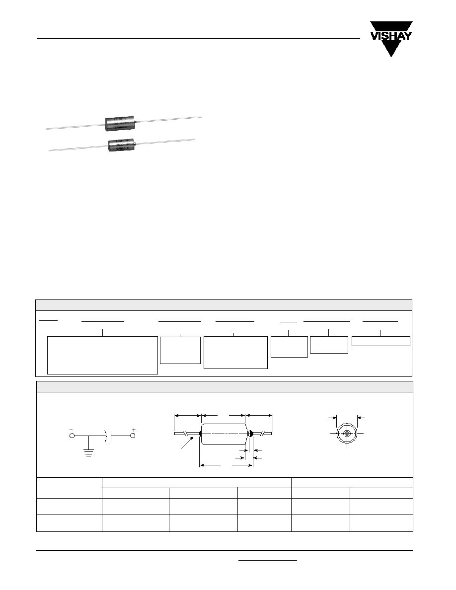
DIMENSIONS
in inches [millimeters]
D
Dia.
L
J
Max.
Solid Tinned
Leads
0.047 [1.19] Max.
0.125 [3.18] Max.
WITH INSULATING SLEEVE*
LEAD SIZE
CASE CODE
R
S
D
0.289
±
0.016
[7.34
±
0.41]
0.351
±
0.016
[8.92
±
0.41]
L
0.686
±
0.031
[17.42
±
0.79]
0.786
±
0.031
[19.96
±
0.79]
AWG NO.
22
22
J (MAX.)
0.822
[20.88]
0.922
[23.42]
NOM. DIA.
0.025
[0.64]
0.025
[0.64]
1.500
±
0.250
[38.10
±
6.35]
1.500
±
0.250
[38.10
±
6.35]
FEATURES
∑ Hermetically-sealed, axial-lead solid tantalum capacitors
∑ Small size and long life
∑ Exceptional capacitance stability and excellent resistance
to severe environmental conditions
∑ The military equivalent is the CSR21 which is qualified to
MIL-C-39003/09
APPLICATIONS
Designed for power supply filtering applications at above
100kHz
At + 85
∞
C: Leakage current shall not exceed 10 times the
values listed in the Standard Ratings Tables.
At +125
∞
C: Leakage current shall not exceed 15 times the
values listed in the Standard Ratings Tables.
Life Test: Capacitors shall withstand rated DC voltage
applied at + 85
∞
C for 2000 hours or derated DC voltage
applied at + 125
∞
C for 1000 hours.
Following the life test:
1. DCL shall not exceed 125% of the initial requirement.
2. Dissipation Factor shall meet the initial requirement.
3. Change in capacitance shall not exceed
±
5%.

www.vishay.com
25
550D
Vishay Sprague
Document Number: 40017
Revision 11-Nov-04
For technical questions, contact tantalum@vishay.com
0.300
0.275
0.250
0.230
0.210
0.190
0.175
0.160
*Insert capacitance tolerance code "X5" for
±
5% units (special order).
R
R
R
R
R
R
R
S
6 WVDC @ + 85
∞
C, SURGE = 8 V . . . 4 WVDC @ + 125
∞
C, SURGE = 5 V
10 WVDC @ + 85
∞
C, SURGE = 13 V . . . 7 WVDC @ + 125
∞
C, SURGE = 9 V
82
100
120
150
180
220
15 WVDC @ + 85
∞
C, SURGE = 20 V . . . 10 WVDC @ + 125
∞
C, SURGE = 12 V
56
68
82
100
120
150
20 WVDC @ + 85
∞
C, SURGE = 26 V . . . 13 WVDC @ + 125
∞
C, SURGE = 16 V
27
33
39
47
56
68
82
100
35 WVDC @ + 85
∞
C, SURGE = 46 V . . . 23 WVDC @ + 125
∞
C, SURGE = 28 V
8.2
10
12
15
18
22
27
33
39
47
50 WVDC @ + 85
∞
C, SURGE = 65 V . . . 33 WVDC @ + 125
∞
C, SURGE = 40 V
550D825X0035R2
550D106X0035R2
550D126X0035R2
550D156X0035R2
550D186X0035R2
550D226X0035R2
550D276X0035S2
550D336X0035S2
550D396X0035S2
550D476X0035S2
550D825X9035R2
550D106X9035R2
550D126X9035R2
550D156X9035R2
550D186X9035R2
550D226X9035R2
550D276X9035S2
550D336X9035S2
550D396X9035S2
550D476X9035S2
550D566X9015R2
550D686X9015R2
550D826X9015S2
550D107X9015S2
550D127X9015S2
550D157X9015S2
8
10
12
15
18
20
CAPACITANCE
(
µ
F)
CASE
CODE
MAX. DCL
@ + 25
∞
C
(
µ
A)
MAX. ESR
@ + 25
∞
C
100kHz
(Ohms)
MAX. DF
@ + 25
∞
C
1kHz
(%)
PART NUMBER*
CAP. TOL.
±
20%
PART NUMBER*
CAP. TOL.
±
10%
R
R
R
S
S
S
550D826X0010R2
550D107X0010R2
550D127X0010R2
550D157X0010S2
550D187X0010S2
550D227X0010S2
550D826X9010R2
550D107X9010R2
550D127X9010R2
550D157X9010S2
550D187X9010S2
550D227X9010S2
8
10
12
15
18
20
8
8
8
8
8
10
0.085
0.075
0.070
0.065
0.060
0.055
150
180
220
270
330
R
R
S
S
S
550D157X0006R2
550D187X0006R2
550D227X0006S2
550D277X0006S2
550D337X0006S2
550D157X9006R2
550D187X9006R2
550D227X9006S2
550D277X9006S2
550D337X9006S2
9
11
12
13
15
10
10
10
10
12
0.065
0.060
0.055
0.050
0.045
0.100
0.095
0.085
0.075
0.070
0.065
6
6
6
8
8
8
550D566X0015R2
550D686X0015R2
550D826X0015S2
550D107X0015S2
550D127X0015S2
550D157X0015S2
R
R
S
S
S
S
R
R
R
R
S
S
S
S
550D276X0020R2
550D336X0020R2
550D396X0020R2
550D476X0020R2
550D566X0020S2
550D686X0020S2
550D826X0020S2
550D107X0020S2
550D276X9020R2
550D336X9020R2
550D396X9020R2
550D476X9020R2
550D566X9020S2
550D686X9020S2
550D826X9020S2
550D107X9020S2
5
7
8
9
11
14
16
20
5
5
5
6
6
6
6
8
0.145
0.130
0.120
0.110
0.100
0.095
0.085
0.075
0.250
0.230
0.210
0.190
0.175
0.160
0.145
0.130
0.120
0.110
4
4
4
4
4
4
4
5
5
5
3
4
4
5
6
8
9
11
14
16
R
R
R
R
R
R
S
S
S
S
5.6
6.8
8.2
10.0
12.0
15.0
18.0
22.0
550D565X0050R2
550D685X0050R2
550D825X0050R2
550D106X0050R2
550D126X0050R2
550D156X0050R2
550D186X0050R2
550D226X0050S2
550D565X9050R2
550D685X9050R2
550D825X9050R2
550D106X9050R2
550D126X9050R2
550D156X9050R2
550D186X9050R2
550D226X9050S2
4
4
5
5
6
8
9
11
3
3
3
3
3
3
4
4
STANDARD RATINGS
Solid-Electrolyte T
ANTALEX
Æ
Capacitors
for High Frequency Power Supplies
Document Number: 40017
Revision 11-Nov-04
www.vishay.com
26
550D
Vishay Sprague
For technical questions, contact tantalum@vishay.com
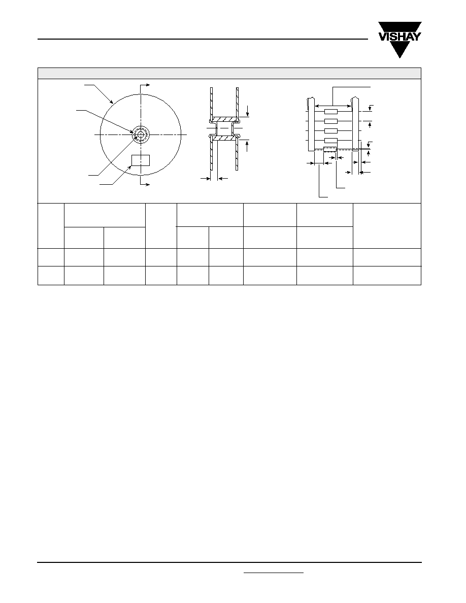
LEAD SIZE
TYPE 550D UNITS WITH
INSULATING SLEEVE
CASE
CODE
R
S
1.374 to 3.626
[34.9 to 92.1]
0.750 [19.05]
SECTION "A" - "A"
TAPE AND REEL PACKAGING
in inches [millimeters]
13 [330.2]
STANDARD REEL
"A"
"A"
1.126 to 3.07
[28.6 to 78.0]
I.D. REEL HUB
LABEL (4.a)
UNITS PER REEL
B
2.875
±
0.062
[73.03
±
1.57]
2.875
±
0.062
[73.03
±
1.57]
COMPONENT
SPACING
A
0.400
±
0.015
[10.16
±
0.38]
0.400
±
0.015
[10.16
±
0.38]
NOM. DIA.
0.025
[0.64]
0.025
[0.64]
AWG NO.
22
22
J (MAX.)
0.822
[20.88]
0.922
[23.42]
L
0.686
±
0.031
[17.42
±
0.79]
0.786
±
0.031
[19.96
±
0.79]
D
0.289
±
0.016
[7.34
±
0.41]
0.351
±
0.016
[8.92
±
0.41]
TAPE
SPACING
500
500
0.625
±
0.062
[15.88
±
1.57]
DIA. THRU HOLE
0.125 [3.18] MAX.
B
TAPE SPACING
COMPONENT
SPACING
A
0.031 [0.79] (3.f)
(BOTH SIDES) ( 3.f)
0.250 [6.35] (3.b)
0.047 [1.19] MAX.
OFF CENTER
(1.a)
Solid-Electrolyte T
ANTALEX
Æ
Capacitors
for High Frequency Power Supplies
STANDARD REEL PACKAGING INFORMATION
1. Component Leads:
a. Component leads shall not be bent beyond 0.047"
[1.19mm] maximum from their nominal position when
measured from the leading edge of the component lead
at the inside tape edge and at the lead egress from the
component.
b. The 'C' dimension shall be governed by the overall length
of the reel packaged component. The distance between
flanges shall be 0.125" to 0.250" [3.18mm to 6.35mm]
greater than the overall component length.
2. Orientation:
a. All polarized components must be oriented to one
direction. The cathode lead tape shall be a color and the
anode lead tape shall be white.
3. Reeling:
a. Components on any reel shall not represent more t h a n
two date codes when date code identification is
required.
b. Component leads shall be positioned between pairs of
0.250" [6.35mm] tape.
c. The disposable reels have hubs with corrugated fiber
board flanges and core or equivalent.
d. A minimum of 12" [304.8mm] leader of tape shall be
provided before the first and after the last component on
the reel.
e. 50 or 60 lb. Kraft paper must be wound between layer of
components as far as necessary for component protection.
Width of paper to be 0.062" to 0.250" [1.57mm to 6.35mm]
less than the 'C' dimension of the reel.
f. A row of components must be centered between tapes
±
0.047" [1.19mm]. In addition, individual components
may deviate from center of component row
±
0.031"
[0.79mm].
g. Staples shall not be used for splicing. Not more than 4
layers of tape shall be used in any splice area and no
tape shall be offset from another by more than 0.031"
[0.79mm] non-cumulative. Tape splices shall overlap at
least 6" [152.4mm] for butt joints and at least 3" [76.2mm]
for lap joints and shall not be weaker than unspliced tape.
Universal splicing clips may also be used.
h. Quantity per reel shall be controlled so that tape
components and cover shall not extend beyond the
smallest dimension of the flange (either across flats or
diameter). Once the quantity per reel for each part number
has been established, future orders for that part number
shall be packaged in that quantity. When order or release
quantity is less than the established quantity, a standard
commercial pack is to be used.
i. A maximum of 0.25% of the components per reel quantity
may be missing without consecutive missing components.
j. Adequate protection must be provided to prevent physical
damage to both reel and components during shipment
and storage.
4. Marking:
a. Minimum reel and carton marking shall consist of the
following: Customer Part Number, Purchase Order No.,
Quantity, Package Date, Manufacturer's name, Electrical
Value, Date Code, Vishay Sprague Part Number and
Country of Origin.

www.vishay.com
27
550D
Vishay Sprague
Document Number: 40017
Revision 11-Nov-04
For technical questions, contact tantalum@vishay.com
TYPICAL CURVES @ + 25∞C, IMPEDANCE AND ESR VS FREQUENCY
1
0.1
.01
FREQUENCY IN HERTZ
100 1K 10K 100K 1M 10M
10
180
µ
F, 6 V
180
µ
F, 6 V
IMPEDANCE
ESR
330
µ
F, 6 V
330
µ
F, 6 V
1
0.1
.01
FREQUENCY IN HERTZ
100 1K 10K 100K 1M 10M
10
IMPEDANCE
ESR
120
µ
F, 10 V
220
µ
F, 10 V
120
µ
F, 10 V
220
µ
F, 10 V
1
0.1
.01
FREQUENCY IN HERTZ
100 1K 10K 100K 1M 10M
10
IMPEDANCE
ESR
150
µ
F, 15 V
68
µ
F, 15 V
150
µ
F, 15 V
68
µ
F, 15 V
1
0.1
.01
FREQUENCY IN HERTZ
100 1K 10K 100K 1M 10M
10
IMPEDANCE
ESR
100
µ
F, 20 V
47
µ
F, 20 V
47
µ
F, 20 V
100
µ
F, 20 V
1
0.1
.01
FREQUENCY IN HERTZ
100 1K 10K 100K 1M 10M
10
IMPEDANCE
ESR
47
µ
F, 35 V
22
µ
F, 35 V
22
µ
F, 35 V
47
µ
F, 35 V
1
0.1
.01
FREQUENCY IN HERTZ
100 1K 10K 100K 1M 10M
10
IMPEDANCE
ESR
22
µ
F, 50 V
18
µ
F, 50 V
22
µ
F, 50 V
18
µ
F, 50 V
OHMS
OHMS
OHMS
OHMS
OHMS
OHMS

Document Number: 40017
Revision 11-Nov-04
www.vishay.com
28
550D
Vishay Sprague
For technical questions, contact tantalum@vishay.com
PERFORMANCE CHARACTERISTICS
1.
Operating Temperature: Capacitors are designed
to operate over the temperature range of - 55
∞
C to
+85
∞
C with no derating.
1.1
Capacitors may be operated up to + 125
∞
C with voltage
derating to two-thirds the + 85
∞
C rating.
2.
DC Working Voltage: The DC working voltage is the
maximum operating voltage for continuous duty at the
rated temperature.
3.
Surge Voltage: The surge DC rating is the maximum
voltage to which the capacitors may be subjected
under any conditions, including transients and peak
ripple at the highest line voltage.
3.1
Surge Voltage Test: Capacitors shall withstand the
surge voltage applied in series with a 33 ohm
±
5%
resistor at the rate of one-half minute on, one-half
minute off, at + 85
∞
C, for 1000 successive test cycles.
3.2
Following the surge voltage test, the dissipation factor
and the leakage current shall meet the initial
requirements; the capacitance shall not have changed
more than
±
10%.
4.
Capacitance Tolerance: The capacitance of all
capacitors shall be within the specified tolerance limits
of the nominal rating.
4.1
Capacitance measurements shall be made by means
of polarized capacitance bridge. The polarizing
voltage shall be of such magnitude that there shall be
no reversal of polarity due to the AC component. The
maximum voltage applied to capacitors during
measurement shall be 2 volts rms at 1000Hz at + 25
∞
C.
If the AC voltage applied is less than one-half volt rms,
no DC bias is required. Measurement accuracy of the
bridge shall be within
±
2%.
5.
Capacitance Change With Temperature: The
capacitance change with temperature shall not
exceed the following percentage of the capacitance
measured at + 25%
6.
Dissipation Factor: The dissipation factor,
determined from the expression 2
fRC, shall not
exceed values listed in the Standard Ratings Table.
6.1
Measurements shall be made by the bridge method
at, or referred to, a frequency of 1000Hz and a
temperature of + 25
∞
C.
7.
Leakage Current: Capacitors shall be stabilized at
the rated temperature for 30 minutes. Rated voltage
shall be applied to capacitors for 5 minutes using a
steady source of power (such as a regulated power
supply) with 1000 ohm resistor connected in series with
the capacitor under test to limit the charging current.
Leakage current shall then be measured.
Note that the leakage current varies with applied voltage. See graph
below for the appropriate adjustment factor.
7.1
At + 25
∞
C, the leakage current shall not exceed the
value listed in the Standard Ratings Table.
7.2
At + 85
∞
C, the leakage current shall not exceed 10
times the value listed in the Standard Ratings Table.
7.3
At + 125
∞
C, the leakage current shall not exceed 15
times the value listed in the Standard Ratings Table.
8.
Life Test: Capacitors shall withstand rated DC voltage
applied at + 85
∞
C for 2000 hours or rated DC voltage
applied at + 125
∞
C for 1000 hours.
8.1
Following the life test, the dissipation factor shall meet
the initial requirement; the capacitance change shall
not exceed
±
2%; the leakage current shall not exceed
125% of the original requirement.
- 55
∞
C
- 10%
+ 85
∞
C
+ 8%
+ 125
∞
C
+ 12%
WORKING
SURGE
WORKING
SURGE
VOLTAGE
VOLTAGE
VOLTAGE
VOLTAGE
(V)
(V)
(V)
(V)
6
8
4
5
10
13
7
9
15
20
10
12
20
26
13
16
35
46
23
28
50
65
33
40
+ 85
∞
C Rating
+ 125
∞
C Rating
TYPICAL LEAKAGE CURRENT FACTOR RANGE
1.0
0.8
0.7
0.6
0.5
0.4
0.3
0.2
0.1
0.08
0.07
0.06
0.05
0.04
0.03
0.02
0.01
0.008
0.007
0.006
0.005
0.004
0.003
0.002
0.001
LEAKAGE CURRENT F
ACT
OR
0
PERCENT OF RATED VOLTAGE
10
30
20
90
40
50
60
70
80
100
At
+ 25
∞
C