Document Number: 42035
Revision 17-Nov-03
www.vishay.com
102
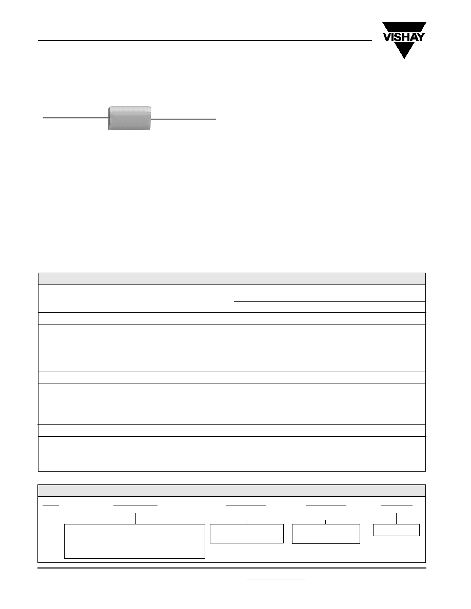
Type 732P
Vishay Sprague
For technical questions, contact spresale@vishay.com
FEATURES
∑ High stability
∑ High ripple current to 30A
∑ Low inductance and low ESR
∑ Excellent AC performance
Film Capacitors
Metalized Polypropylene,
Wrap-and-Fill
ORDERING INFORMATION
732P
TYPE
105
CAPACITANCE
X9
CAPACITANCE
TOLERANCE
200
DC VOLTAGE
RATING
L
TERMINAL
X9 = ± 10% (Inventoried)
X5 = ± 5%
This is expressed in
volts.
* Leads are bare, solid tinned copper wire. Lead wire sizes are:
Case diameter < .700" [17.78mm], lead AWG No. 20.
L = Wire leads*
This is expressed in picofarads. The first two
digits are the significant figures. The third is the
number of zeros to follow. Values must conform
to the decade rating for the tolerance specified.
STANDARD RATINGS in inches [millimeters]
CAP.
(
µ
F)
MAXIMUM RIPPLE CURRENT (Amps rms) @ 20kHz - 100kHz
Case Temperature @
200 WVDC
4.5
5.3
5.9
8.7
8.2
10.0
11.4
5.4
6.5
7.3
8.5
10.3
12.8
600 WVDC
0.713 x 1.500 [18.11 x 38.10]
0.895 x 1.750 [22.73 x 44.45]
1.086 x 1.750 [27.58 x 44.45]
1.192 x 2.250 [30.28 x 57.15]
1.668 x 2.250 [42.37 x 57.15]
1.0
2.0
3.0
5.0
10.0
* Part Numbers listed are for a capacitance tolerance of ± 10%. To specify ± 5% tolerance, change the "X9" in the Part Number to "X5".
7.1
8.7
9.8
11.4
14.1
1.0
2.0
3.0
5.0
10.0
20.0
30.0
PART NUMBER*
±
10%
TOLERANCE
732P105X9200L
732P205X9200L
732P305X9200L
732P505X9200L
732P106X9200L
732P206X9200L
732P306X9200L
0.531 x 0.750 [13.49 x 19.05]
0.596 x 0.938 [15.14 x 23.83]
0.717 x 0.938 [18.21 x 23.83]
0.733 x 1.250 [18.62 x 31.75]
0.898 x 1.500 [22.81 x 38.10]
1.000 x 2.250 [25.40 x 57.15]
1.200 x 2.250 [30.48 x 57.15]
CASE SIZE
D (Max.) x L
±
0.062 [1.57]
Max. ESR
(Milliohms)
20kHz -
100kHz
+ 85
∞
C
4.9
5.8
6.5
7.4
9.0
11.1
12.4
6.0
7.0
8.0
9.0
11.0
13.6
15.0
7.0
8.2
9.4
10.4
12.7
15.0
15.0
15.0
12.0
11.0
10.0
9.0
8.0
6.0
+ 75
∞
C
+ 65
∞
C
+ 55
∞
C
+ 45
∞
C
7.8
9.1
10.3
11.6
14.2
15.0
15.0
+ 35
∞
C
8.5
10.0
11.2
12.7
15.0
15.0
15.0
+ 25
∞
C
9.2
10.8
12.1
13.8
15.0
15.0
15.0
400 WVDC
1.0
2.0
3.0
5.0
10.0
20.0
732P105X9400L
732P205X9400L
732P305X9400L
732P505X9400L
732P106X9400L
732P206X9400L
0.512 x 1.250 [13.00 x 31.75]
0.698 x 1.250 [17.73 x 31.75]
0.747 x 1.500 [18.97 x 38.10]
0.862 x 1.750 [21.89 x 44.45]
1.030 x 2.250 [26.16 x 57.15]
1.440 x 2.250 [36.58 x 57.15]
5.9
7.1
8.0
9.3
11.3
14.1
7.2
8.7
9.8
11.4
13.8
15.0
7.3
10.1
11.3
13.1
15.0
15.0
7.8
9.5
10.7
12.5
15.0
9.5
11.6
13.1
15.0
15.0
9.5
13.4
15.0
15.0
15.0
9.5
15.0
15.0
15.0
15.0
7.3
11.3
12.6
14.7
15.0
15.0
7.3
12.0
13.8
15.0
15.0
15.0
9.5
15.0
15.0
15.0
15.0
7.3
12.0
15.0
15.0
15.0
15.0
9.5
15.0
15.0
15.0
15.0
19.0
15.0
12.0
10.0
6.0
20.0
15.0
13.0
11.0
9.0
6.0
732P105X9600L
732P205X9600L
732P305X9600L
732P505X9600L
732P106X9600L
PERFORMANCE CHARACTERISTICS
Operating Temperature: - 55∞C to + 105∞C.
Capacitance Range: 1.0µF to 30.0µF.
Capacitance Tolerance: ± 10, ± 5%.
Voltage Rating: 200 WVDC to 600 WVDC.
Dissipation Factor: .10% maximum.
Equivalent Series Resistance: 20kHz - 100kHz (see
Standard Ratings table).
Voltage Test: 200% of rated voltage for 2 minutes.
V/
T: 10 volts/microsecond maximum.
Insulation Resistance: At + 25∞C, 100,000
Megohm - Microfarads or 200,000 Megohm minimum.
ENVIRONMENTAL CHARACTERISTICS
Vibration Test (Condition B): No mechanical damage,
short, open or intermittent circuits.
DC Life Test: 140% of rated DC voltage for 250 hours at
+ 105∞C. No open or short circuits. No visible damage
evident. Maximum Capacitance Change: ± 1.0%.
Minimum IR = 50% of initial limit. Maximum DF = .10%.
Humidity Test: 95% relative humidity at + 40∞C for 250
hours. No visible damage evident. Maximum
Capacitance Change: ± 1.0%. Minimum IR = 20% of initial
limit. Maximum DF = .12%.
PHYSICAL CHARACTERISTICS
Lead Pull: 5 pounds (2.3 kilograms) for one minute.
No physical damage.
Lead Bend: After three complete consecutive bends,
no damage.
Marking: Sprague
Æ
trademark, type or part number,
capacitance and voltage.
