 | –≠–ª–µ–∫—Ç—Ä–æ–Ω–Ω—ã–π –∫–æ–º–ø–æ–Ω–µ–Ω—Ç: 84068 | –°–∫–∞—á–∞—Ç—å:  PDF PDF  ZIP ZIP |

VISHAY
Document Number 84068
Rev. 7, 07-Jan-03
Vishay Semiconductors
www.vishay.com
1
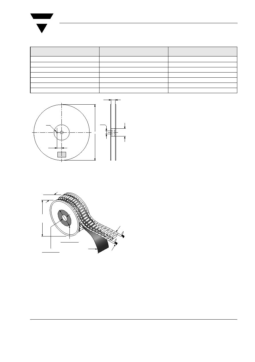
Tape and Reel Standards
Taping Specifications SOD57 and SOD64 Package
Package
Available Packaging
10¥¥ tape & reel
13¥¥ tape & reel
Ammo Pack #1
Ammo Pack #2
Quantity / Reel
Quantity / Reel
Quantity / Box
Quantity / Box
SOD57
5.000
5.000
SOD64
2.500
2.500
DO204AP(G1)
4.500
3.000
G3
1.600
1.000
G4
2.000
2.000
Description
Symbol
Specification (mm)
Component Pitch
A
5.0
± 0.5
Inside Tape Spacing
B
52 + 2 mm - 1 mm
Lead to Lead Eccentricity
ID1-D2I
1.4 max
Lead Extension
K
0
Lead Bending
M
1.2 max
Cumulative Pitch
P
2.0 per 10 pitch
Exposed Adhesive
S
0.8 max
Tape Width
T
6.0
± 0.4
Tape Leader
Beginning and end of reel or ammo pack.
300.0 min
Empty Spaces
Consecutive missing components not allowed
< 0.1 %
Polarity Marking
All polarized components shall be oriented in the same direction.
The cathode tape shall be colored, and anode tape shall be white or light beige.
D
1
D
2
A
P
E
K
S
T
B
W
|D
1
≠ D
2
| = 1.4 (0.055) max.
0.8 (0.031) max.
0.8
(0.031)
max.
Dimensions A, M, K, P, S and T apply to both sides
6.0 ± 0.4
(0.236 ± 0.0157)
15802
Figure 1.

www.vishay.com
2
Document Number 84068
Rev. 7, 07-Jan-03
VISHAY
Vishay Semiconductors
Taping Specification DO204AP(G1), G3 and G4 Packages
Package
Component Spacing ``A`` (Lead to Lead)
Inside Tape Spacing``B"
Cumulative Pitch Tolerance
DO204AP(G1)
5.0 mm + 0.5 mm
(0.197``
± 0.020``)
52.4 mm + 1.5 mm/ - 0.4 mm
(2.062`` + 0.059``/ - 0.016``)
Not to Exceed
1.5 mm (0.059``) over 6
Consecutive
Components
G3, G4
10 mm + 0.5 mm
(0.394``
± 0.020``)
52.4 mm + 1.5 mm/ - 0.4 mm
(2.062`` + 0.059``/ - 0.016``)
(< 68.2 mm)
< 1.2 mm
16959
Figure 2.
VISHAY
Document Number 84068
Rev. 7, 07-Jan-03
Vishay Semiconductors
www.vishay.com
3
10`` Reel Specification (SOD57 and SOD64 Packages)
13`` Reel Specification (DO204AP(G1), G3 and G4 Packages)
Description
Symbol
Reel Size
10``
Arbor Hole Diameter
D
0
30
± 1 mm
Reel Diameter
D2
250
± 2 mm
Drive Hole Diameter
D3
10
± 1 mm
Reel Width
W1
68
± 1 mm
Drive / Arbor Hole Spacing
W2
27.5
± 1 mm
Core Material
Plastic
Reel Material
Plastic
Figure 3.
D
0
D
1
W
1
15 801
W
2
D
2
D
3
Figure 4.
91.9 (3.62) Dia.
50.8 (2.00) Dia.
38.1 (1.50) Dia.
14.3 (0.56) Dia.
Kraft
Paper
Anode Lead
White Tape
Cathode Lead
Colored Tape
C
13.0 Inch/
330 mm
16960

www.vishay.com
4
Document Number 84068
Rev. 7, 07-Jan-03
VISHAY
Vishay Semiconductors
Ammopack #1 Specification (SOD57 and SOD64 Packages) (Figure 5. )
Ammopack #2 Specification (DO204AP(G1), G3 and G4 Packages) ( Figure 6. )
Description
Symbol
Specification
Inches
Millimeters
Length
A
10.25 ± 0.2
260
± 5.0
Width
B
2.75
± 0.2
70
± 5.0
Height
C
5.75
± 0.65
146
± 16.0
Material: corrugated board (neutral)
Figure 5.
A
C
15800
Inspection hole
(both sides)
B
Dimension ``A``
Dimension ``B``
Dimension ``C``
10.0``
(255 mm)
3.15``
(80 mm)
4.53``
(115 mm)
Figure 6.
A
B
C
16956

VISHAY
Document Number 84068
Rev. 7, 07-Jan-03
Vishay Semiconductors
www.vishay.com
5
Preformed Leads (SOD64 Packages)
Some types of automatic insertion machines have
problems in bending the relatively thick leads of
SOD64 Sinterglass Diodes. To overcome this, our
diodes can be ordered with preformed leads as fol-
lows. Preformed Sinterglass Diodes are shipped in
bulk.
SUFFIX RA
SUFFIX RAP
SUFFIX RAS
Common bending version:
Other bending versions are available on request.
Figure 7.
Figure 8.
Figure 9.
Suffix
A (mm)
H (mm)
RA 15/10
RAS 15/10
RAP 15/10
15
10
RA 17.5/ 10
RAS 17.5/ 10
RAP 17.5/ 10
17.5
10