 | –≠–ª–µ–∫—Ç—Ä–æ–Ω–Ω—ã–π –∫–æ–º–ø–æ–Ω–µ–Ω—Ç: DRTOP50 | –°–∫–∞—á–∞—Ç—å:  PDF PDF  ZIP ZIP |
www.vishay.com
27
RTOP
Vishay Sfernice
Document Number: 50045
Revision 14-Jan-04
For technical questions, contact sfer@vishay.com
MECHANICAL SPECIFICATIONS
Mechanical Protection
Insulated case
Substrate
Alumina on insulated base
Resistive Element
Cermet
End Connection
V connections: screw M4 x 6
Tightening Torque Connections 1 Nm
Tightening Torque Heatsink 2 Nm
ENVIRONMENTAL SPECIFICATIONS
Temperature Range
- 55∞C to + 125∞C
Climatic Category
55/125/56
Power Resistors for Mounting onto a Heatsink
Thick Film Technology
FEATURES
∑ 1% tolerance available
∑ High power rating
∑ Wide ohmic value range
∑ Non inductive
∑ Easy mounting
∑ Low thermal radiation of the case
∑ Standard Isotop case (SOT 227 B)
This series of thick film power resistors include modules which can incorporate up to 2 different resistor values in the same SOT
227B package. Two types of terminations are available along with a 4 terminal device for measurement applications in the case
of the single resistor version. This product range benefits from Vishay Sfernice's experience in thick film power resistor technol-
ogy i.e high power: volume ratio, low tolerance or individual resistors and excellent overload capabilities (due to the trimming
technique).
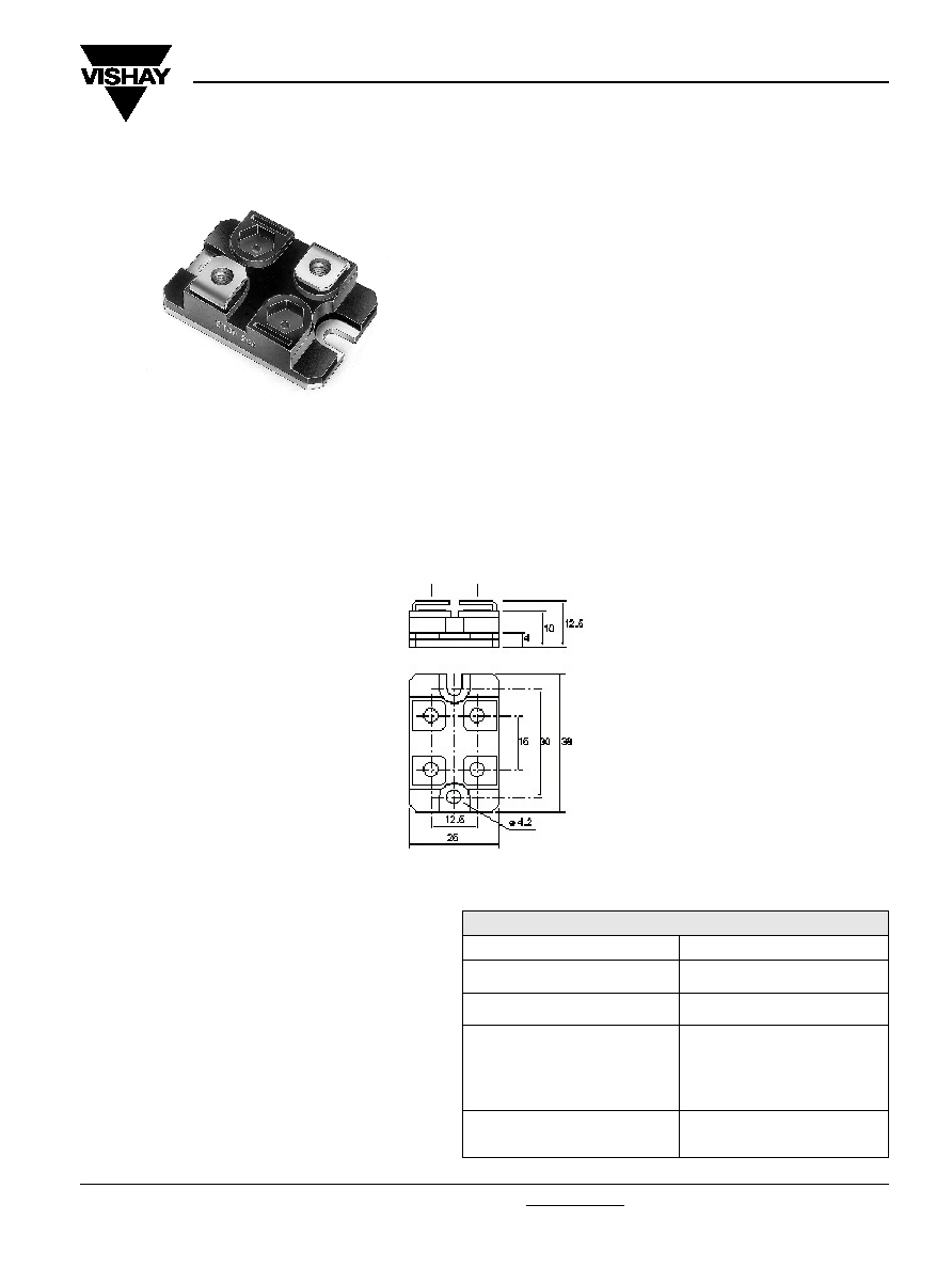
V Connections
RTOP
∑ Tolerances unless otherwise specified: ± 0.3mm
DIMENSIONS in millimeters
Resistance Range
0.046 to 1M
Standard Tolerance
± 1% to ± 10%
Power Rating
50W to 200W at + 25∞C
Temperature Coefficient
Standard
± 300 ppm/∞C (R < 1)
± 150 ppm/∞C (R > 1)
Insulation Resistance
> 10
6
M
ELECTRICAL SPECIFICATIONS
Document Number: 50045
Revision 14-Jan-05
www.vishay.com
28
RTOP
Vishay Sfernice
For technical questions, contact sfer@vishay.com
MODEL
RTOP 200
RTOP 100
DRTOP 100
DRTOP 50
Power Rating at + 25∞C
chassis mounted resistors
200W
100W
100W
50W
unmounted resistors
5W
5W
3.5W
3.5W
Thermal Resistance (per resistor)
0.5∞C/W
1∞C/W
0.5∞C/W
1∞C/W
Limiting Voltage
1500V
1500V
500V
500V
Dielectric Strength*
2500V, 1 Minute
2500V, 1 Minute
2500V, 1 Minute
2500V, 1 Minute
connections/chassis
10mA Max
10mA Max
10mA Max
10mA Max
Dielectric Strength*
-
-
2500V, 1 Minute
2500V, 1 Minute
connections/resistors
10mA Max
10mA Max
Ohmic Value Range
0.046 to 1M
0.092 to 1M
Tolerance
± 1% to ± 10%
± 1% to ± 10%
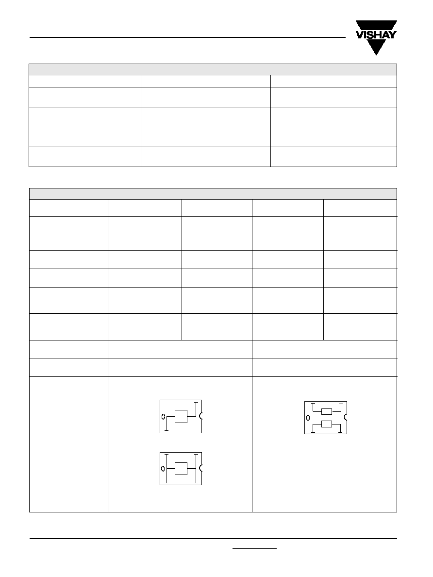
Electrical Diagrams
R
R
R2
R1
SPECIAL FEATURES
Shunt Version
TESTS
CONDITIONS
TYPICAL DRIFTS
Momentary Overload
NF EN 140000 CEI 115_1
< ± (0.25% + 0.05)
2.5Pn/5 seconds
Rapid Temperature Change
NF EN 140000 CEI 68214 Test Na
< ± (0.25% + 0.05)
5 cycles - 55∞C +125∞C
Load Life
NF EN 140000 CEI 115_1
< ± (0.5% + 0.05)
Pn at 25∞C 1000 hours
Humidity (steady state)
MIL STD 202 Method 103 B Test D
< ± (0.5% + 0.05)
56 days 95% R.H.
PERFORMANCE
Power Resistors for Mounting onto a Heatsink
Thick Film Technology
*MIL STD 202 Method 301

www.vishay.com
29
RTOP
Vishay Sfernice
Document Number: 50045
Revision 14-Jan-04
For technical questions, contact sfer@vishay.com
CHOICE OF HEATSINK
The user must choose the heatsink according to the working conditions of the component (power, room temperature).
Maximum working temperature must not exceed 125∞C. The dissipated power is simply calculated by the following ratio:
P =
P:
expressed in W
T: difference between maximum working temperature and room temperature.
R
TH:
(j-c): thermal resistance value measured between resistive layer and outer side of the resistor. It is the thermal
resistance of the component (see Table Special Features).
R
TH:
(c-a): thermal resistance value measured between outer side of the resistor and room temperature. It is the
thermal resistance of the heatsink depending on the heatsink itself (type, shape) and the quality of the fastening
device.
Example:
R
TH:
(c-a) for RTOP 200 power rating 130W at ambient temperature + 30∞C.
Thermal resistance (see table 1) R
TH
(j-c): 0.5∞C/W
T 125∞C - 30∞C - 95∞C
RTH
(
j-c) + RTH
(
c-a) = = = 0.73∞C/W
RTH
(
j-c) 0.5∞C/W
RTH
(c-a)
0.73∞C/W - 0.5∞C/W 0.23∞C/W
T
[R
TH
(j-c) + R
TH
(c-a)]
(1)
RECOMMENDATIONS FOR MOUNTING ONTO A HEATSINK
Surfaces in contact must be carefully cleaned.
The heatsink must have an acceptable flatness: from 0.05mm to 0.1mm/100mm.
Roughness of the heater must be around 6.3µm.
In order to improve thermal conductivity, surfaces in contact (alumina, heatsink) are laid on with a silicone grease (type SI 340
from RhÙne-Poulenc or Dow 340 from Dow Corning).
Tightening torque on heater: 2 Nm
For the electrical connections, it is recommended to use M4 x 6 screws and if necessary a washer of 1mm thickness. The
recommended screw tightening torque is 1 Nm.
130
T
P
95
Power Resistors for Mounting onto a Heatsink
Thick Film Technology
Document Number: 50045
Revision 14-Jan-05
www.vishay.com
30
RTOP
Vishay Sfernice
For technical questions, contact sfer@vishay.com
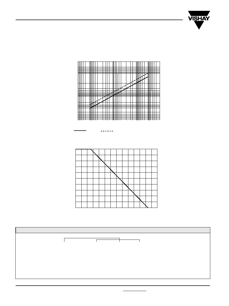
OVERLOADS
The applied power is 2.5 x rated power for 5 s with a max voltage of 2 x nominal voltage.
Accidental overload: The values indicated in the graph below are applicable to resistors in air or mounted onto a heatsink.
In case of multi-resistor devices, (DRTOP, TROP and QROP) the results apply to each resistor value in the device.
POWER RATING CHART
The temperature of the heater should be maintained in the limit specified. To improve the thermal conductivity, surfaces in
contact should be laid on with a silicon grease and the torque applied on the screw for tightening should be around 2 Nm.
MARKING
Series, style, ohmic value (in ), tolerance (in %), manufacturing date, VISHAY trade mark.
% RA
TED PO
WER
0
20
40
60
80
100
120
140
HEATSINK TEMPERATURE IN DEGREES CELSIUS
ENERGY CURVE
ORDERING INFORMATION
RTOP
200
3.2
± 1%
± %
V
R1
T1
R2
MODEL
STYLE
OHMIC VALUE
CONNECTIONS
CUSTOM DESIGN
RTOP
100
Optional
To be precise
V: Screw
Optional
DRTOP
50
± 1%
for each
VS: RTOP Shunt
± 2%
resistor
± 5 %
± 10 %
ABSOLUTE TOLERANCE PER RESISTOR
Power Resistors for Mounting onto a Heatsink
Thick Film Technology
OVERLOAD DURATION IN SECONDS
ENERGY IN JOULES
1.10
-7
1.10
-6
1.10
-5
1.10
-4
1.10
-3
1.10
-2
1.10
-1
1
RTOP
DRTOP
0.01
0.1
1
10
100
1000
0
20
40
60
80
100