
LH1526AB/ AAC/ AACTR
Document Number 83825
Rev. 1.4, 26-Oct-04
Vishay Semiconductors
www.vishay.com
1
i179034
8
7
6
5
1
2
3
4
S2'
S2
S1
S1'
S2'
S2
S1
S1'
DIP
SMD
Pb
Pb-free
e3
Dual 1 Form A Solid-State Relays
Features
∑ Dual Channel 1 Form A
∑ Extremely Low Operating Current
∑ High-speed Operation
∑ Isolation Test Voltage 5300 V
RMS
∑ Current-limit Protection
∑ High Surge Capability
∑ dc-only Option
∑ Clean, Bounce-free Switching
∑ Low Power Consumption
∑ High-reliability Monolithic Receptor
∑ Surface-mountable
∑ Lead-free component
∑ Component in accordance to RoHS 2002/95/EC
and WEEE 2002/96/EC
Agency Approvals
∑ UL1577, File No. E52744 System Code H or J,
Double Protection
∑ CSA - Certification 093751
∑ BSI/BABT Cert. No. 7980
Applications
General Telecom Switching
- Telephone Line Interface
- On/off Hook
- Ring Relay
- Break Switch
- Ground Start
Battery-powered Switch Applications
Industrial Controls
-Microprocessor Control of Solenoids,
Lights, Motors, Heaters, etc.
Programmable Controllers
Instrumentation
See "Solid State Relays" ( Application Note 56)
Description
The LH1526 relay is two SPST normally open
switches that can replace electromechanical relays in
many applications. The relays require a minimal
amount of LED drive current to operate, making it
ideal for battery powered and power consumption
sensitive applications. The relay is constructed using
a GaAIAs LED for actuation control and an integrated
monolithic die for the switch output. The die is, fabri-
cated in a high-voltage dielectrically isolated technol-
ogy, comprised of a photodiode array, switch-control
circuitry, and MOSFET switches. In addition, the relay
employs current-limiting circuitry, enabling it to pass
FCC 68.302 and other regulatory surge requirements
when overvoltage protection is provided. The relay
can be configured for ac/dc or dc-only operation.
Order Information
Part
Remarks
LH1526AAC
Tubes, SMD-8
LH1526AACTR
Tape and Reel, SMD-8
LH1526AB
Tubes, DIP-8
www.vishay.com
2
Document Number 83825
Rev. 1.4, 26-Oct-04
LH1526AB/ AAC/ AACTR
Vishay Semiconductors
Absolute Maximum Ratings, T
amb
= 25 ∞C
Stresses in excess of the absolute Maximum Ratings can cause permanent damage to the device. Functional operation of the device is
not implied at these or any other conditions in excess of those given in the operational sections of this document. Exposure to absolute
Maximum Ratings for extended periods of time can adversely affect reliability.
SSR
Electrical Characteristics, T
amb
= 25 ∞C
Minimum and maximum values are testing requirements. Typical values are characteristics of the device and are the result of engineering
evaluations. Typical values are for information only and are not part of the testing requirements.
Input
Output
Parameter
Test condition
Symbol
Value
Unit
LED input ratings: continuous
forward current
I
F
50
mA
LED input ratings: reverse
voltage
V
R
8.0
V
Output operation: DC or peak
AC load voltage
I
L
50 µA
V
L
400
V
Continuous DC load current ,
unidirectional operation pins 4, 6
(+) to pin 5 (-)
I
L
250
mA
Continuous DC load current ,
two pole operation
I
L
100
mA
Ambient operating temperature
range
T
amb
- 40 to + 85
∞C
Storage temperature range
T
stg
- 40 to + 150
∞C
Pin soldering temperature
t = 10 s max
T
sld
260
∞C
Input/output isolation test
voltage
t = 1.0 s, I
ISO
= 10
µA max
V
ISO
5300
V
RMS
Power dissipation
P
diss
600
mW
Parameter
Test condition
Symbol
Min
Typ.
Max
Unit
LED forward current,
switch turn-on
I
L
= 70 mA, t = 10 ms
I
Fon
0.3
0.5
mA
LED forward current,
switch turn-off
V
L
= ± 350 V, t = 100 ms
I
Foff
0.001
0.1
mA
LED forward voltage
I
F
= 1.5 mA
V
F
0.80
1.15
1.40
V
Parameter
Test condition
Symbol
Min
Typ.
Max
Unit
ON-resistance: ac/dc, each pole I
F
= 1.5 mA, I
L
= ± 50 mA
R
ON
17
25
36
Off-resistance
I
F
= 0 mA, V
L
= ± 100 V
R
OFF
5000
G
Current limit
I
F
= 1.5 mA, t = 5.0 ms,
V
L
= 7.0 V
I
LMT
170
210
270
mA
Off-state leakage current
I
F
= 0 mA, V
L
= ± 100 V
I
O
0.04
200
nA
I
F
= 0 mA, V
L
= ± 400 V
I
O
1.0
µA
Output capacitance
I
F
= 0 mA, V
L
= 1.0 V
C
O
37
pF
I
F
= 0 mA, V
L
= 50 V
C
O
13
pF
Switch offset
I
F
= 5.0 mA
V
OS
0.25
µV
LH1526AB/ AAC/ AACTR
Document Number 83825
Rev. 1.4, 26-Oct-04
Vishay Semiconductors
www.vishay.com
3
Transfer
Typical Characteristics (Tamb = 25
∞C unless otherwise specified)
Parameter
Test condition
Symbol
Min
Typ.
Max
Unit
Capacitance (input-output)
V
ISO
= 1.0 V
C
IO
0.8
pF
Turn-on time
I
F
= 1.5 mA, I
L
= 50 mA
t
on
1.00
ms
I
F
= 5.0 mA, I
L
= 50 mA
t
on
0.5
1.0
ms
Turn-off time
I
F
= 1.5 mA, I
L
= 50 mA
t
off
0.20
ms
I
F
= 5.0 mA, I
L
= 50 mA
t
off
0.4
0.9
ms
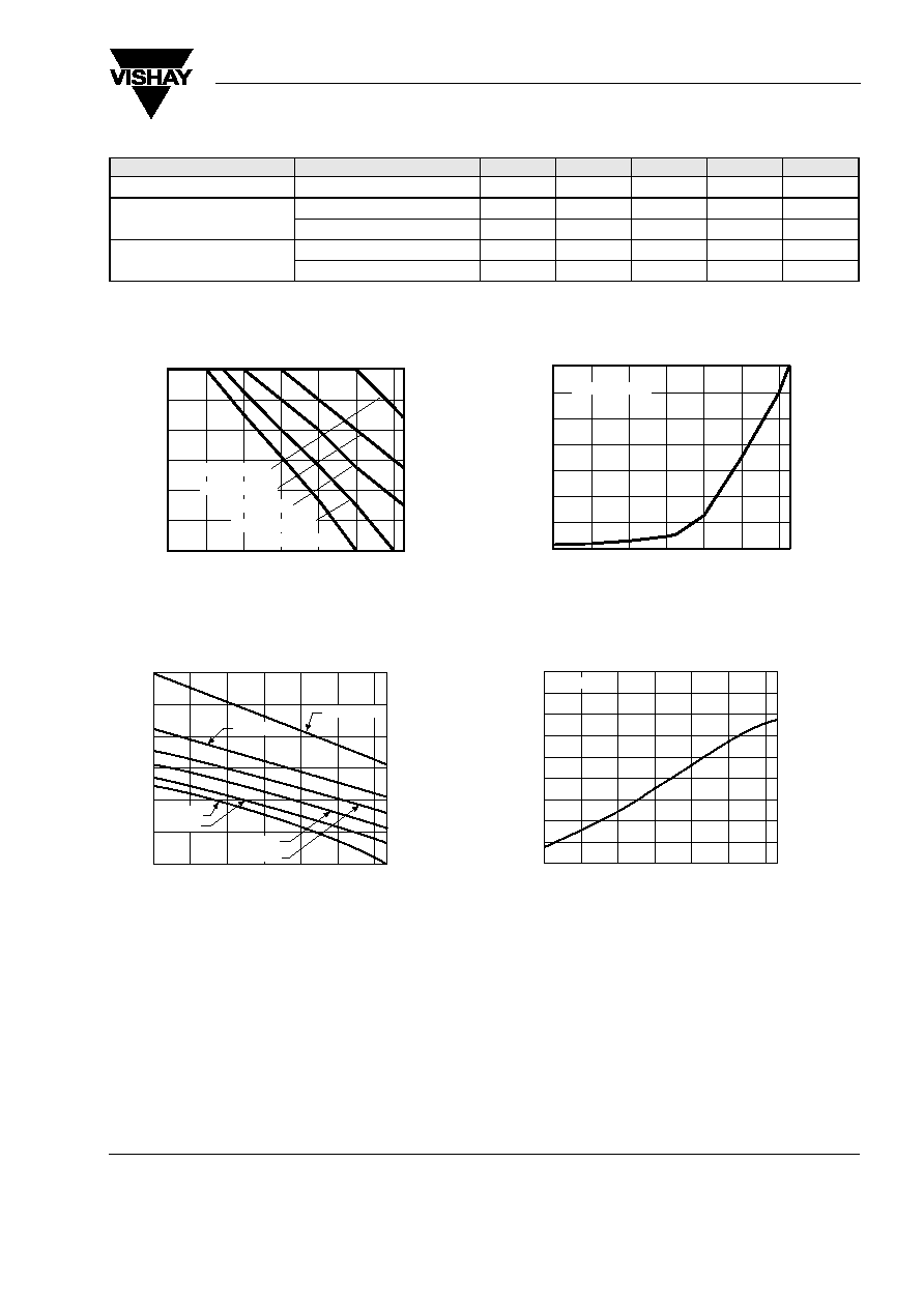
Figure 1. Recommended Operating Conditions
Figure 2. LED Voltage vs. Temperature
0
20
40
60
80
100
120
≠40
≠20
0
20
40
60
80
Ambient Temperature ( ∞C )
17333
I
Fon
= 5 to10 mA
Load
Current
(
m
A
)
I
Fon
= 1 mA
I
Fon
= 2 mA
I
Fon
= 0.5 mA
I
Fon
= 0.3 mA
ilh1526ab_01
AMBIENT TEMPERATURE, TA (∞C)
LED
FORWAD
VOLTAGE
(V)
-40
-20
0
20
40
60
80
1.6
1.5
1.4
1.3
1.2
1.1
1.0
IF = 20 mA
IF = 1 mA
IF = 2 mA
IF = 5 mA
IF = 10 mA
IF = 50 mA
Figure 3. LED Current for Switch Turn-on vs. Temperature
Figure 4. ON-Resistance vs. Temperature
≠100
100
300
500
700
900
1100
1300
≠40
≠20
0
20
40
60
80
Ambient Temperature ( ∞C )
17332
I
L
= 100 mA
T
u
rn≠on
(%),
Norm.
to
25
C
∞
LED
Forward
Current
for
Switch
ilh1526ab_03
50
40
30
20
10
0
-10
-20
-30
-40
-40
-20
0
20
40
60
80
AMBIENT TEMPERATURE, TA (∞C)
CHANGE
IN
ON-RESISTANCE
(%)
NORMALZED
TO
25
∞
C
IL = 50 mA

www.vishay.com
4
Document Number 83825
Rev. 1.4, 26-Oct-04
LH1526AB/ AAC/ AACTR
Vishay Semiconductors
Figure 5. LED Dropout Voltage vs. Temperature
Figure 6. Current Limit vs. Temperature
Figure 7. Variation in ON-Resistance vs. LED Current
ilh1526ab_04
1.20
1.10
1.00
0.90
0.80
0.70
-40
-20
0
20
40
60
80
AMBIENT TEMPERATURE, TA (∞C)
LED
FORWARD
VOLTAGE
(V)
ilh1526ab_05
40
30
20
10
0
-10
-20
-30
-40
CHANGE
IN
CURRENT
LIMIT
(%)
NORMALIZED
TO
25
∞
C
-40
-20
0
20
40
60
80
AMBIENT TEMPERATURE, TA (∞C)
IF = 5 mA, t = 5 ms
ilh1526ab_06
9
8
7
6
5
4
3
2
1
0
0.0
1.0
2.0
3.0
4.0
5.0
LED FORWARD CURRENT (mA)
ac/dc
ON-RESISTANCE
VARIATION
(%)
NORMALIZED
TO
DATA
SHEET
R
ON
SPECIFICATION
@
I F
=5m
A
Figure 8. Switch Capacitance vs. Applied Voltage
Figure 9. Output Isolation
Figure 10. Leakage Current vs. Applied Voltage at Elevated
Temperatures
ilh1526ab_07
CAPACITNCE
(pF)
0
20
40
60
80
100
APPLIED VOLTAGE (V)
70
60
50
40
30
20
10
0
ilh1526ab_08
FREQUENCY (Hz)
ISOLATION
(dB)
100
80
60
40
20
0
102
103
104
105
106
107
VP = 10 V
RL = 50
ilh1526ab_09
LOAD VOLTAGE (V)
OFF-STATE
LEAKAGE
CURRENT
(nA)
3.5
3.0
2.5
2.0
1.5
1.0
0.5
0.0
0
50
100
150 200
250 300
350 400
70 ∞C
85 ∞C
50 ∞C

LH1526AB/ AAC/ AACTR
Document Number 83825
Rev. 1.4, 26-Oct-04
Vishay Semiconductors
www.vishay.com
5
Figure 11. Insertion Loss vs. Frequency
Figure 12. Leakage Current vs. Applied Voltage
Figure 13. Switch Breakdown Voltage vs. Temperature
ilh1526ab_10
FREQUENCY (Hz)
INSERTION
LOSS
(dB)
0.6
0.5
0.4
0.3
0.2
0.1
0.0
102
103
104
105
RL = 600
ilh1526ab_11
LOAD VOLTAGE (V)
OFF-STATE
LEAKAGE
CURRENT
(pA)
0
50
100
150 200
250 300
350 400
100
90
80
70
60
50
40
30
20
10
0
IF = 0 mA
ilh1526ab_12
AMBIENT TEMPERATURE, TA (∞C)
CHANGE
IN
BREAKDOWN
VOLTAGE
(%)
NORMALIZED
TO
25
∞
C
8
6
4
2
0
-2
-4
-6
-8
-40
-20
0
20
40
60
80
Figure 14. Switch Offset Voltage vs. Temperature
Figure 15. Turn-on Time vs. Temperature
Figure 16. Turn-on Time vs. LED Current
ilh1526ab_13
5
4
3
2
1
0
20
30
40
50
60
70
80
90
AMBIENT TEMPERATURE, TA (∞C)
(
µ
A)
IF = 5 mA
ilh1526ab_14
AMBIENT TEMPERATURE, TA (∞C) (mA)
CHANGE
IN
TURN-0N
TIME
(%)
NORMALIZD
TO
25
∞
C
-40
-20
0
20
40
60
80
60
50
40
30
20
10
0
-10
-20
-30
-40
IF = 5 mA
IL = 50 mA
ilh1526ab_15
LED FORWARD CURRENT (mA)
TURN-ON
TIME
(ms)
0
4
8
12
16
20
3.0
2.4
1.8
1.2
0.6
0.0
85 ∞C
25 ∞C
-40 ∞C