 | –≠–ª–µ–∫—Ç—Ä–æ–Ω–Ω—ã–π –∫–æ–º–ø–æ–Ω–µ–Ω—Ç: TCSS2100 | –°–∫–∞—á–∞—Ç—å:  PDF PDF  ZIP ZIP |
TCSS1100/ TCSS2100
Vishay Telefunken
1 (7)
www.vishay.com
Document Number 83761
Rev. A4, 08≠Jun≠99
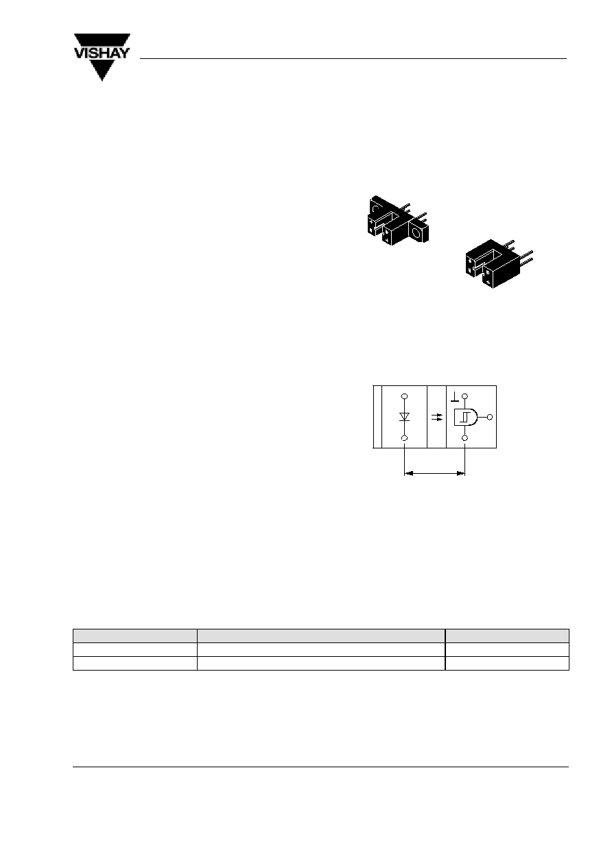
Transmissive Optical Sensor
Description
This device has a compact construction where the
emitting-light sources and the detectors are located
face to face on the same optical axes.
The operating wavelength is 950 nm. The detector
consists of a photologic-IC with Schmitt trigger and
open collector output.
Applications
D
Detection of opaque material, documents etc.
D
Paper position sensor in copy machines
D
Position sensor for shaft encoder
Features
D
Output:
`LOW' when infrared beam is not interrupted
D
Inverter-open collector
D
TTL compatible
D
Built-in voltage regulator
D
Plastic polycarbonate case, protected against
ambient light
D
No adjustment necessary
D
Two package variations
15132
A)
B)
+
_
+
V
O
95 10821
7.6
0.3"
Top view
Handling Precautions
Connect a capacitor C of more than 100 nF between V
S1
and ground in order to stabilize power supply voltage!
Order Instruction
Ordering Code
Resolution (mm) / Aperture (mm)
Remarks
TCSS1100
A)
0.6 / 1.0
No mounting flags
TCSS2100
B)
0.6 / 1.0
With two mounting flags
TCSS1100/ TCSS2100
Vishay Telefunken
www.vishay.com
2 (7)
Rev. A4, 08≠Jun≠99
Document Number 83761
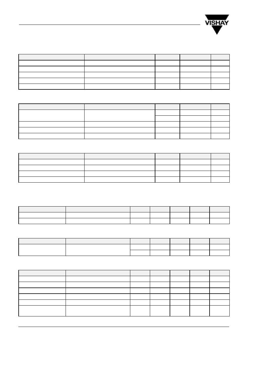
Absolute Maximum Ratings
Input (Emitter)
Parameter
Test Conditions
Symbol
Value
Unit
Reverse voltage
V
R
6
V
Forward current
I
F
60
mA
Forward surge current
t
p
10
m
s
I
FSM
3
A
Power dissipation
T
amb
25
∞
C
P
V
100
mW
Junction temperature
T
j
100
∞
C
Output (Detector)
Parameter
Test Conditions
Symbol
Value
Unit
Supply voltages
V
S1
6.5
V
V
S2
18
V
Output current
I
O
20
mA
Power dissipation
T
amb
25
∞
C
P
V
250
mW
Junction temperature
T
j
100
∞
C
Coupler
Parameter
Test Conditions
Symbol
Value
Unit
Total power dissipation
T
amb
25
∞
C
P
tot
250
mW
Ambient temperature range
T
amb
≠25 to +85
∞
C
Storage temperature range
T
stg
≠40 to +100
∞
C
Soldering temperature
2 mm from case, t
5 s
T
sd
260
∞
C
Electrical Characteristics
(T
amb
= 25
∞
C)
Input (Emitter)
Parameter
Test Conditions
Symbol
Min.
Typ.
Max.
Unit
Forward voltage
I
F
= 50 mA
V
F
1.25
1.6
V
Junction capacitance
V
R
= 0, f = 1 MHz
C
j
50
pF
Output (Detector)
Parameter
Test Conditions
Symbol
Min.
Typ.
Max.
Unit
Supply voltage range
V
S1
4.75
5.25
V
V
S2
4.0
16
V
Coupler
Parameter
Test Conditions
Symbol
Min.
Typ.
Max.
Unit
Supply current
V
S1
= 16 V
I
S1
3
5
mA
Output current
V
S1
= V
S2
= 16 V, I
F
= 0
I
OH
1
m
A
Input threshold current V
S1
= 5 V
I
FT
5
10
mA
Hysteresis
V
S1
= 5 V
I
Foff
/I
Fon
80
%
Output voltage
I
OL
= 16 mA, I
F
I
TF
, V
S1
= 5 V
V
OL
0.15
0.4
V
Switching frequency
I
F
3x I
FT
, V
S1
= V
S2
= 5 V,
R
L
= 1 k
W
f
sw
200
kHz
TCSS1100/ TCSS2100
Vishay Telefunken
3 (7)
www.vishay.com
Document Number 83761
Rev. A4, 08≠Jun≠99
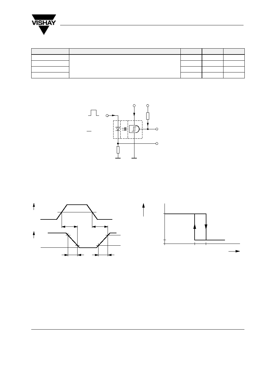
Switching Characteristics
Parameter
Test Conditions
Symbol
Typ.
Unit
Rise time
V
S1
= V
S2
= 5 V, I
F
= 3 x I
FT
, R
L
= 1 k
W
(see figure 1)
t
r
50.0
ns
Turn-on time
S1
S2
F
FT
L
t
on
1.0
m
s
Fall time
t
f
20.0
ns
Turn-off time
t
off
3.0
m
s
Channel I
Channel II
I
F
3 x I
F
0
95 10791
I
O
V
S1
= 5 V
I
S1
V
O
R
L
270
(1 k
)
V
S2
= 5 V (16 V)
R
G
= 50
W
t
p
t
p
= 50
m
s
T
= 0.01
50
W
Oscilloscope
R
L
y
1 M
W
C
L
x
20 pF
Figure 1. Test circuit for: t
r
, t
on
, t
f
, t
off
50%
o
t
on
Channel II
o
90%
10%
95 10819
Channel I
t
off
I
F
V
O
t
f
t
r
Figure 2. Pulse diagram
V
O
95 10820
HIGH
LOW
0.8
1.0
I
Foff
I
Fon
I
Frel
Figure 3. Hysteresis
TCSS1100/ TCSS2100
Vishay Telefunken
www.vishay.com
4 (7)
Rev. A4, 08≠Jun≠99
Document Number 83761
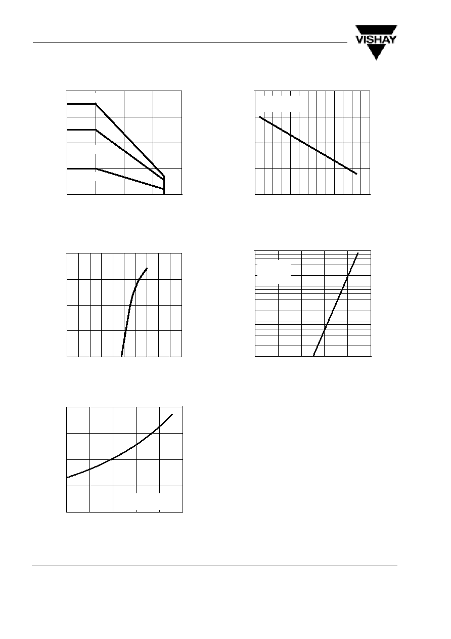
Typical Characteristics
(T
amb
= 25
_
C, unless otherwise specified)
0
100
200
300
400
0
25
50
75
100
96 11945
P
≠
T
otal Power Dissipation ( mW
)
tot
T
amb
≠ Ambient Temperature (
∞
C )
Coupled device
Photodetector
IR-diode
Figure 4. Total Power Dissipation vs.
Ambient Temperature
0.1
1.0
10.0
100.0
1000.0
0
0.2 0.4 0.6 0.8 1.0 1.2 1.4 1.6 1.8 2.0
V
F
≠ Forward Voltage ( V )
96 11862
F
I ≠ Forward Current ( mA
)
Figure 5. Forward Current vs. Forward Voltage
≠25
0
25
50
0
0.5
1.0
2.0
I ≠ Relative
Threshold
Forward
Current
FT
rel
T
amb
≠ Ambient Temperature (
∞
C )
100
95 11080
1.5
75
V
S1
=V
S2
=5V
R
L
=1k
W
Figure 6. Relative Threshold Forward Current vs.
Ambient Temperature
0.8
0.9
1.0
1.1
1.2
≠30≠20≠10 0 10 20 30 40 50 60 70 80 90 100
T
amb
≠ Ambient Temperature (
∞
C )
96 11946
V
S1
=V
S2
=5V
R
L
=1k
W
I ≠ Relative Supply Current
Srel
Figure 7. Relative Supply Current vs.
Ambient Temperature
≠25
0
25
50
75
1
10
100
1000
I ≠ High Level Output Current ( nA
)
OH
T
amb
≠ Ambient Temperature (
∞
C )
100
95 11079
V
S1
=5V
V
S2
=20V
I
F
=0
Figure 8. High Level Output Current vs.
Ambient Temperature
TCSS1100/ TCSS2100
Vishay Telefunken
5 (7)
www.vishay.com
Document Number 83761
Rev. A4, 08≠Jun≠99
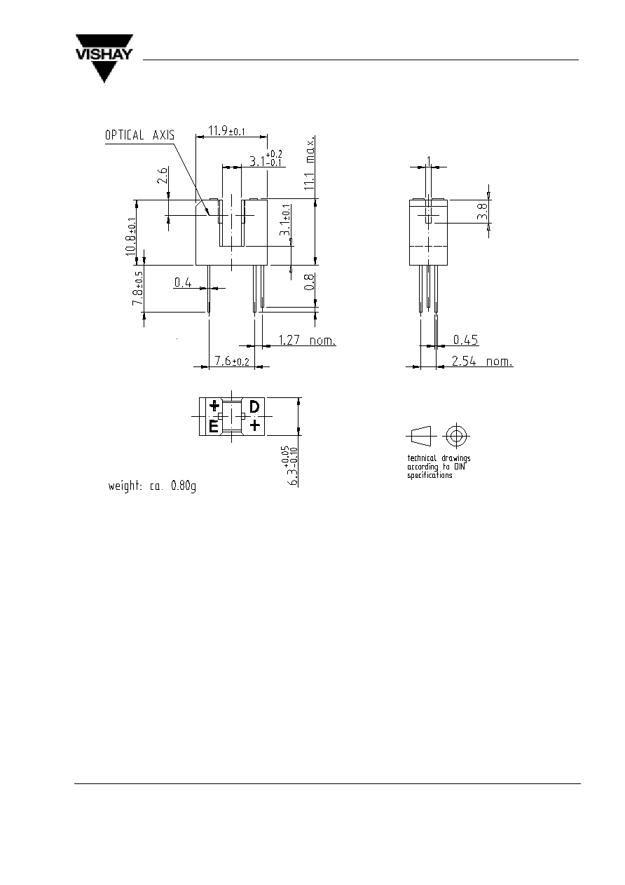
Dimensions of TCSS1100 in mm
96 12096