
TZX...
Vishay Telefunken
Rev. 2, 01-Apr-99
1 (7)
www.vishay.de
∑
FaxBack +1-408-970-5600
Document Number 85614
Silicon Epitaxial Planar Z≠Diodes
Features
D
Very sharp reverse characteristic
D
Low reverse current level
D
Very high stability
D
Low noise
D
Available with tighter tolerances
Applications
Voltage stabilization
94 9367
Absolute Maximum Ratings
T
j
= 25
_
C
Parameter
Test Conditions
Type
Symbol
Value
Unit
Power dissipation
l=4mm, T
L
=25
∞
C
P
V
500
mW
Z≠current
I
Z
P
V
/V
Z
mA
Junction temperature
T
j
175
∞
C
Storage temperature range
T
stg
≠65...+175
∞
C
Maximum Thermal Resistance
T
j
= 25
_
C
Parameter
Test Conditions
Symbol
Value
Unit
Junction ambient
l=4mm, T
L
=constant
R
thJA
300
K/W
Electrical Characteristics
T
j
= 25
_
C
Parameter
Test Conditions
Type
Symbol
Min
Typ
Max
Unit
Forward voltage
I
F
=200mA
V
F
1.5
V
TZX...
Vishay Telefunken
Rev. 2, 01-Apr-99
4 (7)
www.vishay.de
∑
FaxBack +1-408-970-5600
Document Number 85614
Type
V
Zmin.
V
Zmax.
Type
V
Zmin.
V
Zmax.
r
Zmax.
at I
Z
I
Rmax.
at V
R
(V)
(V)
(V)
(V)
(
W
)
(mA)
(
m
A)
(V)
TZX24
22.9
25.5
TZX24C
24.3
25.5
70
2
1
19
TZX27
25.2
28.6
TZX27A
25.2
26.6
80
2
1
21
TZX27
25.2
28.6
TZX27B
26.2
27.6
80
2
1
21
TZX27
25.2
28.6
TZX27C
27.2
28.6
80
2
1
21
TZX30
28.2
31.6
TZX30A
28.2
29.6
100
2
1
23
TZX30
28.2
31.6
TZX30B
29.2
30.6
100
2
1
23
TZX30
28.2
31.6
TZX30C
30.2
31.6
100
2
1
23
TZX33
31.2
34.5
TZX33A
31.2
32.6
120
2
1
25
TZX33
31.2
34.5
TZX33B
32.2
33.6
120
2
1
25
TZX33
31.2
34.5
TZX33C
33.2
34.5
120
2
1
25
TZX36
34.2
38.0
TZX36A
34.2
35.7
140
2
1
27
TZX36
34.2
38.0
TZX36B
35.3
36.8
140
2
1
27
TZX36
34.2
38.0
TZX36C
36.4
38.0
140
2
1
27
Characteristics (T
j
= 25
_
C unless otherwise specified)
95 9611
0
5
10
15
0
100
200
300
400
500
20
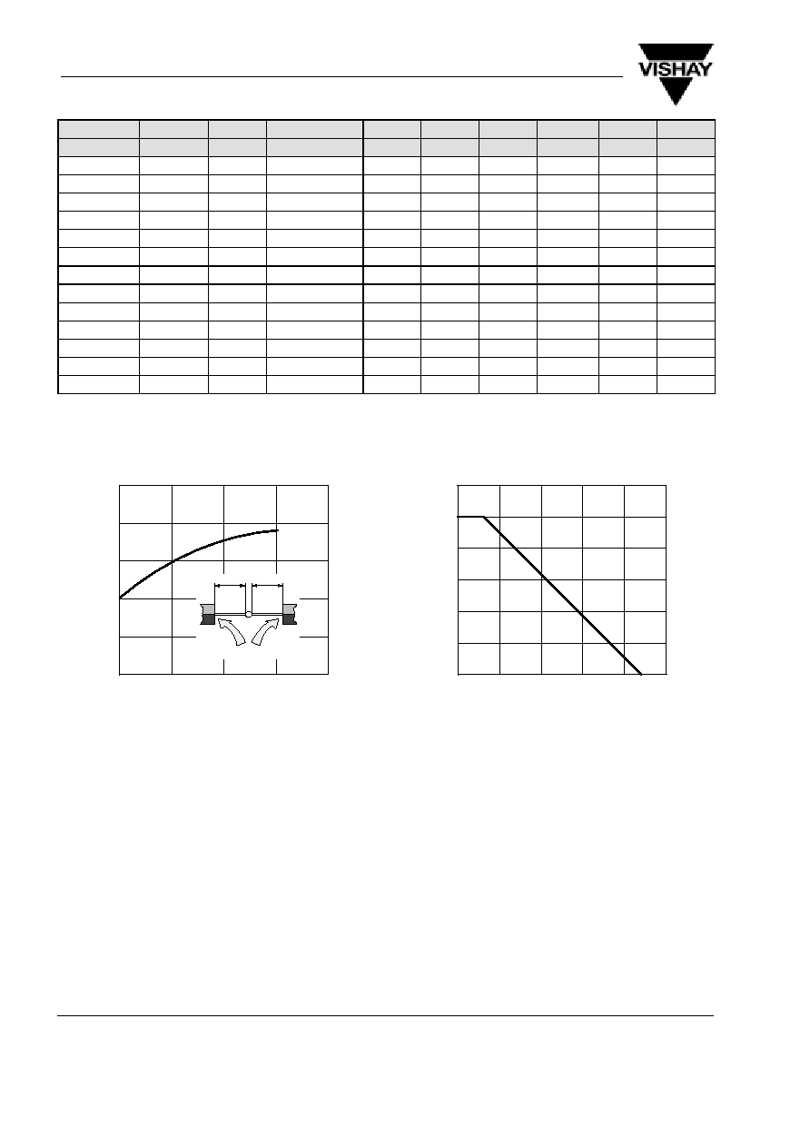
R ≠
Therm. Resist. Junction /
Ambient ( K/W
)
thJA
l ≠ Lead Length ( mm )
l
l
T
L
=constant
Figure 1. Thermal Resistance vs. Lead Length
0
40
80
120
160
0
100
300
400
500
600
P
≠
T
otal Power Dissipation ( mW
)
tot
T
amb
≠ Ambient Temperature (
∞
C )
200
95 9602
200
Figure 2. Total Power Dissipation vs.
Ambient Temperature

TZX...
Vishay Telefunken
Rev. 2, 01-Apr-99
5 (7)
www.vishay.de
∑
FaxBack +1-408-970-5600
Document Number 85614
0
5
10
15
20
1
10
100
1000
V
≠
V
oltage
Change
(
mV
)
Z
V
Z
≠ Z-Voltage ( V )
25
95 9598
D
I
Z
=5mA
T
j
= 25
∞
C
Figure 3. Typical Change of Working Voltage under
Operating Conditions at T
amb
=25
∞
C
≠60
0
60
120
180
0.8
0.9
1.0
1.1
1.2
1.3
V
≠ Relative
V
oltage
Change
Ztn
T
j
≠ Junction Temperature (
∞
C )
240
95 9599
V
Ztn
=V
Zt
/V
Z
(25
∞
C)
TK
VZ
=10
10
≠4
/K
8
10
≠4
/K
≠4
10
≠4
/K
6
10
≠4
/K
4
10
≠4
/K
2
10
≠4
/K
≠2
10
≠4
/K
0
Figure 4. Typical Change of Working Voltage vs.
Junction Temperature
0
10
20
30
≠5
0
5
10
15
TK ≠
T
emperature
Coef
ficient of
V
( 10 /K
)
VZ
V
Z
≠ Z-Voltage ( V )
50
95 9600
40
Z
≠4
I
Z
=5mA
Figure 5. Temperature Coefficient of Vz vs.
Z≠Voltage
0
5
10
15
0
50
100
150
200
C ≠ Diode Capacitance ( pF )
D
V
Z
≠ Z-Voltage ( V )
25
95 9601
20
T
j
= 25
∞
C
V
R
= 2V
Figure 6. Diode Capacitance vs.
Z≠Voltage
0
0.2
0.4
0.6
0.8
0.001
0.01
0.1
1
10
100
1.0
95 9605
I ≠ Forward Current ( mA
)
F
V
F
≠ Forward Voltage ( V )
T
j
= 25
∞
C
Figure 7. Forward Current vs.
Forward Voltage
0
4
8
12
16
20
95 9604
0
20
40
60
80
100
I ≠ Z-Current ( mA
)
Z
V
Z
≠ Z-Voltage ( V )
P
tot
=500mW
T
amb
=25
∞
C
Figure 8. Z≠Current vs. Z≠Voltage

