
ZTE1.5 thru ZTE5.1
Vishay Semiconductors
formerly General Semiconductor
Document Number 88425
www.vishay.com
02-May-02
1
Features
∑ Silicon Stabilizer Diodes
∑ Monolithic integrated analog circuits designed for
small power stabilizer and limitation circuits,
providing low dynamic resistance and high-quality
stabilization performance as well as low noise. In the
reverse direction, these devices show the behavior of
forward-biased silicon diodes.
∑ The end of the ZTE device marked with the cathode ring
is to be connected: ZTE1.5 and ZTE2 to the negative
pole of the supply voltage; ZTE2.4 thru ZTE5.1 to the
positive pole of the supply voltage.
∑ These diodes are also available in MiniMELF case with
the type designation LL1.5 ... LL 5.1.
Mechanical Data
Case: DO-35 Glass Case
Weight: approx. 0.13g
Packaging codes/options:
D7/10K per 13" reel (52mm tape), 20K/box
D8/10K per Ammo tape, (52mm tape), 20K/box
DO-204AH (DO-35 Glass)
mi
n. 1.083 (
27.5)
mi
n. 1.083
(
2
7
.
5)
max
. .
150 (
3.8)
max.
Cathode
.020 (0.52)
Mark
max.
.079 (2.0)
Dimensions are in inches
and (millimeters)
Maximum Ratings
(T
A
= 25∞C unless otherwise noted)
Parameter
Symbol
Value
Unit
Operating Current (see Table "Characteristics")
Inverse Current
I
F
100
mA
Power dissipation at T
amb
= 25∞C
P
tot
300
(1)
mW
Junction temperature
T
J
150
∞C
Storage temperature range
T
S
≠ 55 to +150
∞C
Electrical and Thermal Characteristics
(T
A
= 25∞C unless otherwise noted)
Parameter
Symbol
Min.
Typ.
Max.
Unit
Forward Voltage at I
F
= 10 mA
V
F
≠
≠
1.1
V
Temperature Coefficient of the
ZTE1.5, ZTE2
VZ
≠
≠26
≠
10
≠4
/∞C
stabilized voltage at I
Z
= 5 mA
ZTE2.4, ZTE5.1
VZ
≠
≠34
≠
10
≠4
/∞C
Thermal resistance junction to ambient air
R
JA
≠
≠
400
(1)
∞C/W
Voltage Stabilizers

ZTE1.5 thru ZTE5.1
Vishay Semiconductors
formerly General Semiconductor
www.vishay.com
Document Number 88425
2
02-May-02
Electrical Characteristics
(T
A
= 25∞C unless otherwise noted)
Operating Voltage
Dynamic resistance
Permissable operating current
at I
Z
= 5mA
(2)
at I
Z
= 5mA
at T
amb
= 25∞C
(1)
Type
V
Z
(
)
r
zj
(
)
I
Z
max. (mA)
ZTE1.5
1.35 ... 1.55
13(<20)
120
ZTE2
2.0 ... 2.3
18(<30)
120
ZTE2.4
2.2 ... 2.56
14(<20)
120
ZTE2.7
2.5 ... 2.9
15(<20)
105
ZTE3
2.8 ... 3.2
15(<20)
95
ZTE3.3
3.1 ... 3.5
16(<20)
90
ZTE3.6
3.4 ... 3.8
16(<25)
80
ZTE3.9
3.7 ... 4.1
17(<25)
75
ZTE4.3
4.0 ... 4.6
17(<25)
65
ZTE4.7
4.4 ... 5.0
18(<25)
60
ZTE5.1
4.8 ... 5.4
18(<25)
55
Notes: (1) Valid provided that electrodes are kept at ambient temperature at a distance of 8mm from case
(2) Tested with pulses t
p
= 5ms
ZTE1.5 thru ZTE5.1
Vishay Semiconductors
formerly General Semiconductor
Document Number 88425
www.vishay.com
02-May-02
3
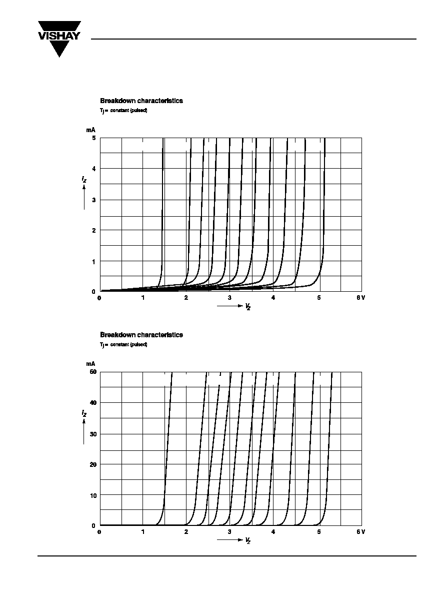
Ratings and
Characteristic Curves
(T
A
= 25∞C unless otherwise noted)
ZTE1.5
ZTE2 2.4 2.7 3.0 3.3 3.6 3.9
4.3
4.7
5.1
ZTE1.5 ... 5.1
ZTE1.5 ... 5.1x
ZTE1.5
ZTE2
2.4 2.7
3
3.3 3.6 3.9
4.3
4.7
5.1
ZTE1.5 thru ZTE5.1
Vishay Semiconductors
formerly General Semiconductor
www.vishay.com
Document Number 88425
4
02-May-02
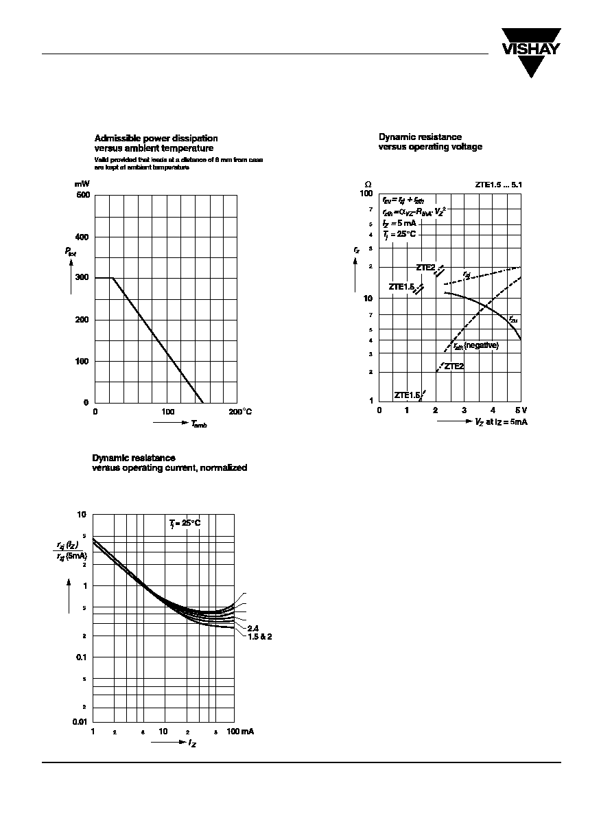
Ratings and
Characteristic Curves
(T
A
= 25∞C unless otherwise noted)
ZTE 1.5 ... 5.1
ZTE1.5 ... 5.1
3
3.6
4.3
5.1
ZTE