 | –≠–ª–µ–∫—Ç—Ä–æ–Ω–Ω—ã–π –∫–æ–º–ø–æ–Ω–µ–Ω—Ç: VSC7212RG | –°–∫–∞—á–∞—Ç—å:  PDF PDF  ZIP ZIP |
VITESSE
SEMICONDUCTOR CORPORATION
VITESSE
SEMICONDUCTOR CORPORATION
Preliminary Data Sheet
VSC7212
Gigabit Interconnect Chip
G52268-0, Rev 3.3
Page 1
04/10/01
© VITESSE
SEMICONDUCTOR CORPORATION ∑ 741 Calle Plano ∑ Camarillo, CA 93012
Tel: (800)-VITESSE ∑ FAX: (805) 987-5896 ∑ Email: prodinfo@vitesse.com
Internet: www.vitesse.com
Features
General Description
The VSC7212 is an 8-bit parallel-to-serial and serial-to-parallel transceiver chip used for high bandwidth
interconnection between busses, backplanes, or other subsystems. A Fibre Channel and Gigabit Ethernet
compliant transceiver provides up to 2.18Gb/s of duplex raw data transfer. The VSC7212 can operate at a
maximum data transfer rate of 1088Mb/s (8 bits at 136MHz) or a minimum rate of 784Mb/s (8 bits at 98MHz).
The VSC7212 contains an 8B/10B encoder, serializer, de-serializer, 8B/10B decoder and elastic buffer which
provide the user with a simple interface for transferring data serially and recovering it on the receive side. The
device can also be configured to operate as a non-encoded 10-bit transceiver with redundant I/O.
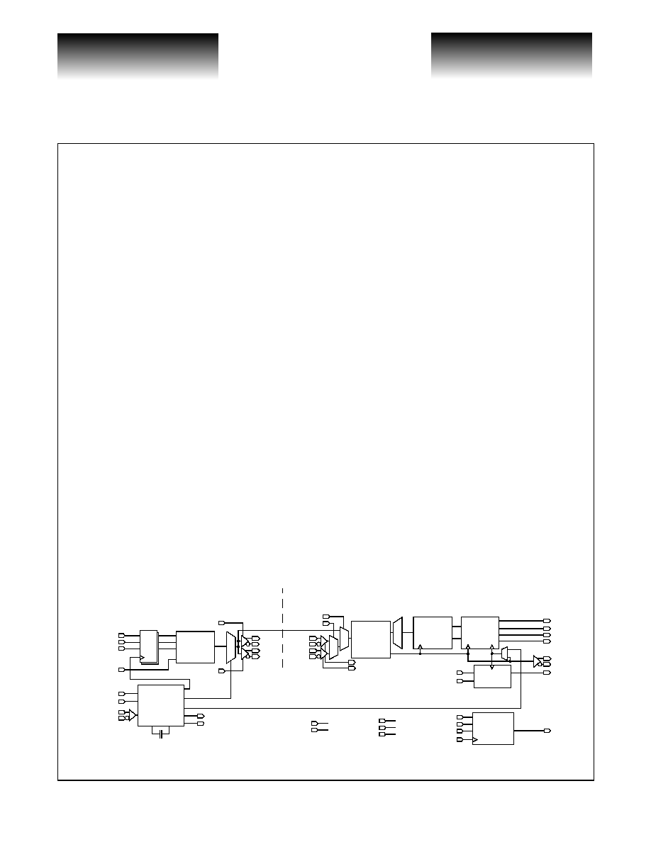
VSC7212 Block Diagram
∑ ANSI X3T11 Compliant Fibre Channel and IEEE
802.3z Compliant Gigabit Ethernet Transceiver
∑ Over 2Gb/s Duplex Raw Data Rate
∑ Redundant PECL Tx Outputs and Rx Inputs
∑ 8B/10B Encoder/Decoder, Optional Encoder/
Decoder Bypass Operation
∑ "ASIC-Friendly
TM
" Timing Options for Transmit-
ter Parallel Input Data
∑ Elastic Buffer for Chip-to-Chip Cable Deskewing
∑ Tx/Rx Rate Matching via IDLE Insertion/Deletion
∑ Compatible with VSC7211, VSC7214 and
VSC7216
∑ Received Data Aligned to Local REFCLK or to
Recovered Clock
∑ PECL Rx Signal Detect and Cable Equalization
∑ Serial Tx-to-Rx and Parallel Rx-to-Tx Internal
Loopback Modes
∑ Clock Multiplier Generates Baud Rate Clock
∑ Automatic Lock-to-Reference
∑ JTAG Boundary Scan Support for TTL I/O
∑ Built-In Self Test
∑ 3.3V Supply, 1.0 W
∑ 100-pin, 14mm TQFP package
x20/x10
Clock Gen
Tx Clock
ENDEC
RESETN
WSI
DUAL
Channel
Align
WSO
TBC
KCHAR
10
Encode
8B/10B
D Q
T(7:0)
C/D
8
8
PTX-
PTX+
RTX-
RTX+
WSEN
RTXEN
PTXEN
PRX-
PRX+
RRX-
RRX+
RXP/R
LBEN(1:0)
Recovery
Clk/Data
Decode
8B/10B
10
Buffer
Elastic
3
8
IDLE
ERR
R(7:0)
KCH
8
RCLKN
RCLK
REFCLKP
REFCLKN
REFCLK
TBERR
TMODE(2:0)
FLOCK
TMS
TRSTN
TDI
TCK
TDO
Boundary
JTAG
Scan
RMODE(1:0)
CAP0 CAP1
TRANSMITTER
RECEIVER
BIST
LBTX
RSDET
PSDET
REFOUT
ESE
SEMICONDUCTOR CORPORATION
VITESSE
SEMICONDUCTOR CORPORATION
Preliminary Data Sheet
VSC7212
Gigabit Interconnect Chip
Page 2
G52268-0, Rev 3.3
04/10/01
© VITESSE
SEMICONDUCTOR CORPORATION ∑ 741 Calle Plano ∑ Camarillo, CA 93012
Tel: (800)-VITESSE ∑ FAX: (805) 987-5896 ∑ Email: prodinfo@vitesse.com
Internet: www.vitesse.com
Notation
Differential signals (i.e., PTX+ and PTX-) may be referred to as a single signal (i.e., PTX) by dropping
reference to the "+" and "- ". REFCLK refers to the single-ended TTL or differential PECL input pair
REFCLKP/REFCLKN, whichever is used.
Clock Synthesizer
Depending on the state of the DUAL input, the VSC7212 clock synthesizer multiplies the reference
frequency provided on the REFCLK input by 10 (DUAL is LOW) or 20 (DUAL is HIGH) to achieve a baud
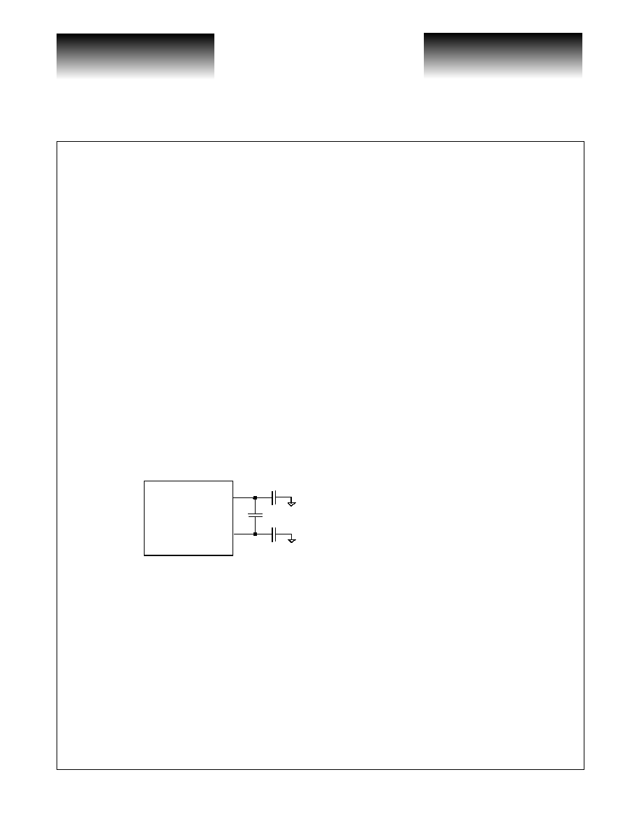
rate clock between 0.98GHz and 1.36GHz. The on-chip PLL uses a single external 0.1µF capacitor, connected
between CAP0 and CAP1, to control the Loop Filter. This capacitor should be a multilayer ceramic dielectric,
or better, with at least a 5V working voltage rating and a good temperature coefficient; NPO is preferred but
X7R may be acceptable. These capacitors are used to minimize the impact of common-mode noise on the Clock
Multiplier Unit, especially power supply noise. Higher value capacitors provide better robustness in systems.
NPO is preferred because if an X7R capacitor is used, the power supply noise sensitivity will vary with
temperature. For best noise immunity, the designer may use a three capacitor circuit with one differential
capacitor between CAP0 and CAP1, C1, a capacitor from CAP0 to ground, C2, and a capacitor from CAP1 to
ground, C3. Larger values are better but 0.1µF is adequate. However, if the designer cannot use a three capacitor
circuit, a single differential capacitor, C1, is adequate. These components should be isolated from noisy traces.
Figure 1: Loop Filter Capacitors (Best Circuit)
The REFCLK signal can be either single-ended TTL or differential LVPECL. If TTL, connect the TTL
input to REFCLKP but leave REFCLKN open. If LVPECL, connect the inputs to REFCLKP and REFCLKN.
Internal biasing resistors sets the proper DC Level to V
DD
/2.
CAP0
CAP1
C1
C2
C3
VSC7216
C1=C2=C3= >0.1µF
MultiLayer Ceramic
Surface Mount
NPO (Preferred) or X7R
5V Working Voltage Rating

VITESSE
SEMICONDUCTOR CORPORATION
VITESSE
SEMICONDUCTOR CORPORATION
Preliminary Data Sheet
VSC7212
Gigabit Interconnect Chip
G52268-0, Rev 3.3
Page 3
04/10/01
© VITESSE
SEMICONDUCTOR CORPORATION ∑ 741 Calle Plano ∑ Camarillo, CA 93012
Tel: (800)-VITESSE ∑ FAX: (805) 987-5896 ∑ Email: prodinfo@vitesse.com
Internet: www.vitesse.com
Transmitter Functional Description
Transmitter Data Bus
The VSC7212 transmitter has an 8-bit input transmit data character, T(7:0), and two control inputs, C/D and
WSEN. The C/D input determines whether a normal data character or a special "K-character" is transmitted,
and the WSEN input initiates transmission of a 16-character "Word Sync Sequence" used to align the receiver.
These data and control inputs are clocked either on the rising edge of REFCLK, on the rising edge of TBC, or
within the data eye formed by TBC ("ASIC-Friendly" timing). The transmit interface mode is controlled by
TMODE(2:0) as shown in Table 1.
When used, TBC must be frequency locked to REFCLK. No phase relationship is assumed. A small skew
buffer is provided to tolerate phase drift between TBC and REFCLK. This buffer is recentered by the RESETN
input, and the total phase drift after recentering must be limited to +/- 180◊ (where 360◊ is one character time).
The VSC7212 has an error output, TBERR, that is asserted HIGH to indicate that the phase drift between TBC
and REFCLK has accumulated to the point that the elastic limit of the skew buffer has been exceeded and a
transmit data character has been either dropped or duplicated. This error can not occur when input timing is
referenced to REFCLK. The TBERR output timing is identical to the low-speed receiver outputs, as selected by
RMODE(1:0) in Table 5.
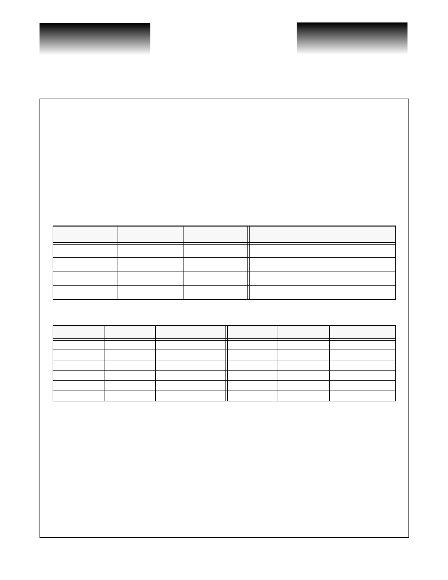
Table 1: Transmit Interface Input Timing Mode
The following figures show the possible relationships between data and control inputs and the selected
input timing source. Figure 2 shows how REFCLK is used as an input timing reference. This mode of operation
is also used in the VSC7211 and VSC7214. Figure 3 and Figure 4 show how TBC is used as an input timing
reference. When TBC is used to define a data eye as shown in Figure 4, it functions as an additional data input
that simply toggles every cycle.
Note that the REFCLK and TBC inputs are not used directly to clock the input data. Instead, an internal
PLL generates edges aligned with the appropriate clock. The arrows on the rising edges of these signals define
the reference edge for the internal phase detection logic. An internal clock is generated at 1/10 the serial
transmit data rate that is locked to the selected input timing source. This is an especially important issue when
DUAL is HIGH and input timing is referenced to REFCLK, since the falling edge is NOT used. The internal
clock active edges are placed coincident with the REFCLK rising edges and halfway between the REFCLK
rising edges in this mode.
TMODE(2:0)
Input Timing Reference
0 0 0
REFCLK Rising Edge
0 0 1
0 1 X
Reserved
1 0 X
TBC Rising Edge
1 1 X
TBC Data Eye

ESE
SEMICONDUCTOR CORPORATION
VITESSE
SEMICONDUCTOR CORPORATION
Preliminary Data Sheet
VSC7212
Gigabit Interconnect Chip
Page 4
G52268-0, Rev 3.3
04/10/01
© VITESSE
SEMICONDUCTOR CORPORATION ∑ 741 Calle Plano ∑ Camarillo, CA 93012
Tel: (800)-VITESSE ∑ FAX: (805) 987-5896 ∑ Email: prodinfo@vitesse.com
Internet: www.vitesse.com
A similar situation exists when TBC is used to define a data eye; only the rising edges of TBC are used to
define the external data timing. The internal clock active edges are placed at 90◊ and 270◊ points between
consecutive TBC rising edges (which are assumed to be 360◊ apart).
Figure 2: Transmit Timing, TMODE(2:0) = 000
Figure 3: Transmit Timing, TMODE(2:0) = 10X
Figure 4: Transmit Timing, TMODE(2:0) = 11X ("ASIC-Friendly" Timing)
REFCLK
(DUAL = 0)
Valid
C/D
Valid
Valid
T(7:0)
WSEN
REFCLK
(DUAL = 1)
Valid
C/D
Valid
Valid
T(7:0)
WSEN
TBC
Valid
C/D
Valid
Valid
T(7:0)
WSEN
TBC
0
o
90
o
180
o
270
o
360
o
VITESSE
SEMICONDUCTOR CORPORATION
VITESSE
SEMICONDUCTOR CORPORATION
Preliminary Data Sheet
VSC7212
Gigabit Interconnect Chip
G52268-0, Rev 3.3
Page 5
04/10/01
© VITESSE
SEMICONDUCTOR CORPORATION ∑ 741 Calle Plano ∑ Camarillo, CA 93012
Tel: (800)-VITESSE ∑ FAX: (805) 987-5896 ∑ Email: prodinfo@vitesse.com
Internet: www.vitesse.com
8B/10B Encoder
The VSC7212 contains an 8B/10B encoder which translates the 8-bit input data on T(7:0) into a 10-bit
encoded data character. A C/D input is also provided which, along with KCHAR, allow the transmission of
special Fibre Channel Kxx.x characters (see Table 2). Note that KCHAR is a static input, and does NOT have
the same input timing as T(7:0), C/D and WSEN. Normally C/D is LOW in order to transmit data. If C/D is
HIGH and KCHAR is LOW, then a Fibre Channel defined IDLE Character (K28.5 = `0011111010' or
`1100000101' depending on disparity) is transmitted and T(7:0) is ignored. If C/D is HIGH and KCHAR is
HIGH, a Kxx.x character is transmitted as determined by the data on T(7:0) (see Table 3). Data patterns other
than those defined in Table 3 produce undefined 10B encodings.
Table 2: Transmit Data Controls
Table 3: Special Characters (Selected when C/D and KCHAR are HIGH)
Encoder Bypass Mode
When ENDEC is LOW the 8B/10B encoder is bypassed and a 10-bit input character T(7:0) is serialized
onto PTX/RTX with bit T0 is transmitted first. The C/D input becomes T8, and WSEN becomes T9. The
KCHAR input becomes ENCDET which is not used in the transmitter, but when HIGH, enables "Comma"
detection in the receiver. Refer to the "Decoder Bypass Mode" section for a description of this mode of
operation in the receiver. The latency through the transmitter is reduced by one character time when ENDEC is
LOW. This mode of operation is similar to a 10-bit interface commonly found in serializer/deserializers for the
Fibre Channel (e.g., VSC7125) and Gigabit Ethernet markets (e.g., VSC7135).
WSEN
C/D
KCHAR
Encoded 10-bit Output
0
0
X
Data Character
0
1
0
IDLE Character (K28.5)
0
1
1
Special Kxx.x Character
1
X
X
16-Character Word Sync Sequence
Code
T(7:0)
Comment
Code
T(7:0)
Comment
K28.0
000 11100
User Defined
K28.6
110 11100
User Defined
K28.1
001 11100
User Defined
K28.7
111 11100
Test Only
K28.2
010 11100
User Defined
K23.7
111 10111
User Defined
K28.3
011 11100
User Defined
K27.7
111 11011
User Defined
K28.4
100 11100
User Defined
K29.7
111 11101
User Defined
K28.5
101 11100
IDLE
K30.7
111 11110
User Defined