Schottky Barrier Diodes
MINI-MELF Outline Dimensions
* Small surface mounting type
* High reliability
* Low reverse current and low forward voltage
* Low current rectification and high speed switching
*Case : MINI-MELF Glass Case (SOD-80)
*Polarity: Color Band Denotescathode Band
*Weight : Approx 0.05 gram
Mechanical Data:
Features:
LL103A/B/C
WEITRON
http//www.weitron.com.tw
Schottky Barrier Diode
350 mAMPERES
20-40 VOLTS
MINI-MELF
Unit:mm
A
B
C
Dim
A
B
C
Min
3.30
1.30
0.28
Max
3.70
1.60
0.50
MINI MELF
Lead(Pb)-Free
P b
1/3
24-Feb-06

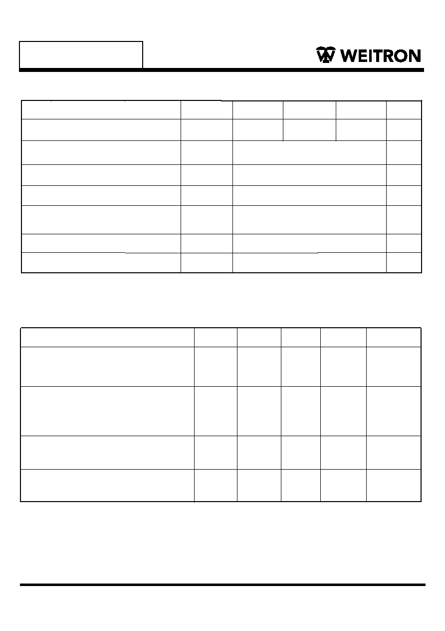
Maximum Ratings
(T
A
=25∞C Unless otherwise noted)
Characteristic
Pepetitive Peak Reverse Voltage
Symbol
V
RRM
I
FSM
LL103A
LL103B
LL103C
Unit
V
A
TJ
TSTG
+175
250
-65 to +175
Electrical Characteristics
(T
A
=25∞C Unless otherwise noted)
Characteristic
Symbol
Min
Tpy
Max
Unit
V
Reverse Recovery Time
IF= IR=200mA to 0.1mA IR
IR
VF
IF
P
D
R
JA
A
m
W
m
∞C
K/W
∞C
Forward Voltage
I
F
= 20mA
I
F
= 200mA
C
D
PF
WEITRON
http//www.weitron.com.tw
Forward Continuous Current, T
A
=25 ∞C
Power dissipation,T
A
=25∞C
Repetitive peak forward current
t
p
1s
Operating Temperature Range
Junction ambient
On PC board 50mm◊50mm◊1.6mm
30
40
1.0
350
400
20
LL103A
LL103B
LL103C
Diode capacitance
VR=VF=0, f=1MHz
Rverse Current
V
R
=30V
V
R
=20V
V
R
=10V
Trr
0.37
0.6
50
-
µA
nS
-
-
-
-
5.0
5.0
5.0
-
-
-
-
-
-
-
-
-
10
Strorage Temperature Range
LL103A/B/C
2/3
24-Feb-06

LL103A/B/C
WEITRON
http//www.weitron.com.tw
Fig. 1 Forward Current vs. Forward Voltage
V F ≠ Forward Voltage ( mV )
Fig. 2 Forward Current vs. Forward Voltage
)
A
(
t
n
e
r
r
u
C
d
r
a
w
r
o
F
≠
I
0
1
2
3
4
5
0.0 0.5 1.0 1.5
V
F
≠ Forward Voltage ( V )
F
Fig. 3 Reverse Voltage vs. Junction Temperature
Fig. 4 Diode Capacitance vs. Reverse Voltage
Fig. 6 Reverse Current vs. Reverse Voltage
T
j
≠ Junction Temperature (∞C )
µA)
(
t
n
e
r
r
u
C
e
s
r
e
v
e
R
≠
I
R
1
10
100
1
0.1
10
100
1000
0 10 20 30 40 50
V
R
≠Reverse Voltage ( V )
0 10 20 30 40 50
V
R
≠Reverse Voltage ( V )
)
F
p
(
e
c
n
a
t
i
c
a
p
a
C
e
d
o
i
D
≠
C
D
Fig. 5 Forward Current vs. Pulse width
t
p
≠ Pulse width ( ms )
Typical Characteristics
(T
A
= 25 ∞C unless otherwise specified)
I
F
Forward Current(mA)
3/3
24-Feb-06
1000
100
10
1
0.1
0.01
0
500
1000
0
100
200
)
A
(
t
n
e
r
r
u
C
d
r
a
w
r
o
F
≠
I
F
0
10
20
30
40
50
0
10
20
30
40
50
0.001 0.01 0.1 1.0 10 100 1000
T
A
=125∞C
I
F
=400mA
I
F
=200mA
I
F
=100mA
T
A
=100∞C
T
A
=75∞C
T
A
=50∞C
T
A
=25∞C
V
R
-Reverse Voltage (V)


