http://www.weitron.com.tw
WEITRON
SM17 thru SM19
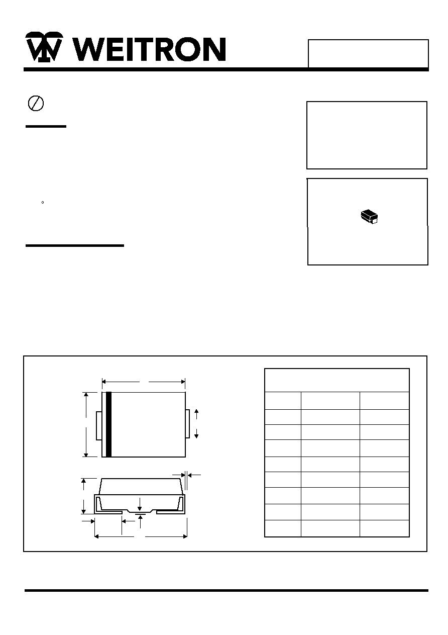
SMA(DO-214AC)
SMA Outline Dimension
Unit:mm
SMA
Dim
Min
Max
A
B
C
D
E
G
H
J
2.20
4.00
1.27
0.15
4.48
0.10
0.76
1.70
2.92
4.60
1.63
0.31
5.59
0.20
1.52
2.62
A
B
C
D
J
G
H
E
SCHOTTKY BARRIER
RECTIFIERS
1.0 AMPERES
20-40 VOLTS
*Low Forward Voltage
*Low Switching Noise
*High Surge Capacity
*Guarantee Reverse Avalance
*Gurad-ing for Stress Protection
*Low Power Loss & High Efficiency
*125 C Operating Junction Temperature
Product Description:
Feature:
Surface Mount Schottky Power Rectifiers
*Low Stored Charge Majority Carrier Conduction
*Case: Epoxy, Molded
Using the Schottky Barrier principle with a Molybdenum barrier metal.
These state-of-are geometry features epitaxial construction with oxide
passivation and metal overlay contact. Ideally suited for low voltage,
high frequency rectification, or as free wheeling and polarity protection
diodes, in surface mount applications where compact size and weight
are critical to the system.
Lead(Pb)-Free
P b

Maximum Rating
Characteristic
Peak Repetitive Reverse Voltage
Working Peak Reverse Voltage
DC Blocking Voltage
RMS Reverse Voltage
Average Rectifier Forward Current
Peak Repetitive Forward Current
(Rate VR,Square Wave, 20 KHz)
Non-Repetitive Peak Square Current
(Surge Applied atRated Load Condition
Halfware, Single Phase, 60Hz)
Operating and Storage Junction
Temperature Range
V
V
V
V
I
I
I
T ,T
SM17
SM18
SM19
UNIT
14
21
28
V
V
1.0
1.0
25
-65 to + 125
A
A
A
C
Characteristic
Electrical Characteristic
Maximum Instantaneous Reverse Current
(Rated DC Voltage, Tc=25 C)
(Rated DC Voltage, Tc=100 C)
Maximum Instanatneous Forward Voltage
(IF=1.0Amp)
Symbol
SM17
SM18 SM19
UNIT
Typical Junction Capacitance
(VR=4.0V, f=1.0MHz)
V
I
C
0.450
0.50
0.50
V
mA
F
0.5
50
50
Symbol
SM17 thru SM19
WEITRON
http://www.weitron.com.tw
P
20
30
40
J STG
P
R
F
FSM
FM
F(AV)
R(RMS)
R
RWM
RRM

WEITRON
http://www.weitron.com.tw
SM17 thru SM19
FIG.1 Forward Current Derating Curve
0 10 20 30 40 50 60 70 80 90 100 110 120 130140
1.2
1
0.8
0.6
0.4
0.2
0
FIG.2 Typical Forward Characteristics
FORWARD VOLTAGE(V)
I
N
S
T
A
N
T
A
N
E
O
U
S
F
O
R
W
A
R
D
C
U
R
R
E
N
T
(
A
M
P
.
)
LEAD TEMPERATURE( C)
A
V
E
R
A
G
E
F
O
R
W
A
R
D
R
E
C
T
I
F
I
E
D
C
U
R
R
E
N
T
(
A
M
P
.
)
10
1
0
0.2
0.4
0.6
0.8
1
1.2
1.4
1.6
1
0.1
FIG.3 Typcial Junction Capacitance
REVERSE VOLTAGE(V)
J
U
N
C
T
I
O
N
C
A
P
A
C
I
T
A
N
C
E
(
F
)
P
1
10
10
100
NUMBER OF CYCLES AT 60Hz
P
E
A
K
F
O
R
W
A
R
D
S
U
R
G
E
C
U
R
R
E
N
T
(
A
M
P
.
)
FIG.4 Peak Forward Surge Current
10
100
0
5
10
15
20
25
30