W541C240 Data Sheet
4-BIT MICROCONTROLLER
Publication Release Date: May 30, 2003
- 1 -
Revision A1
Table of Contents-
1.
GENERAL DESCRIPTION ......................................................................................................... 2
2.
FEATURES ................................................................................................................................. 2
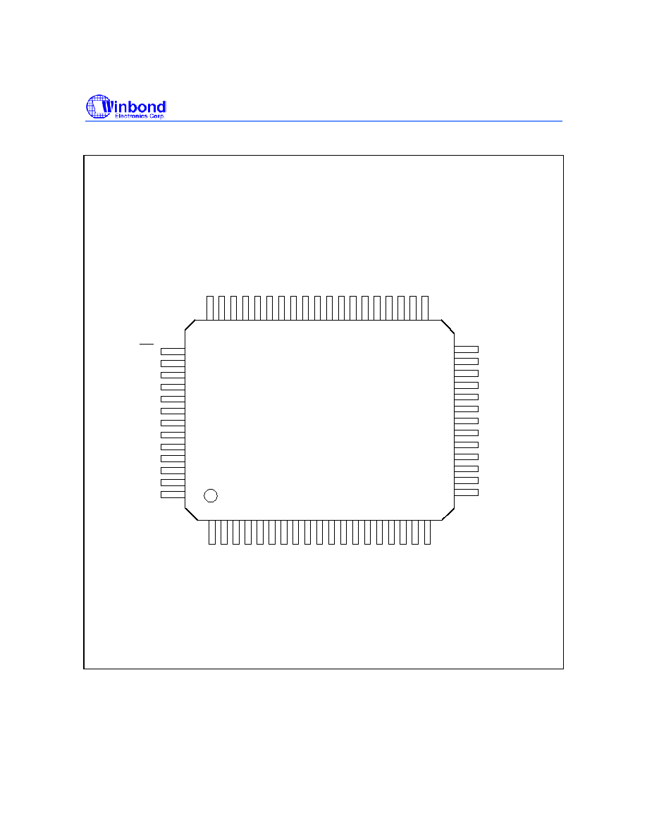
3.
PIN CONFIGURATION............................................................................................................... 4
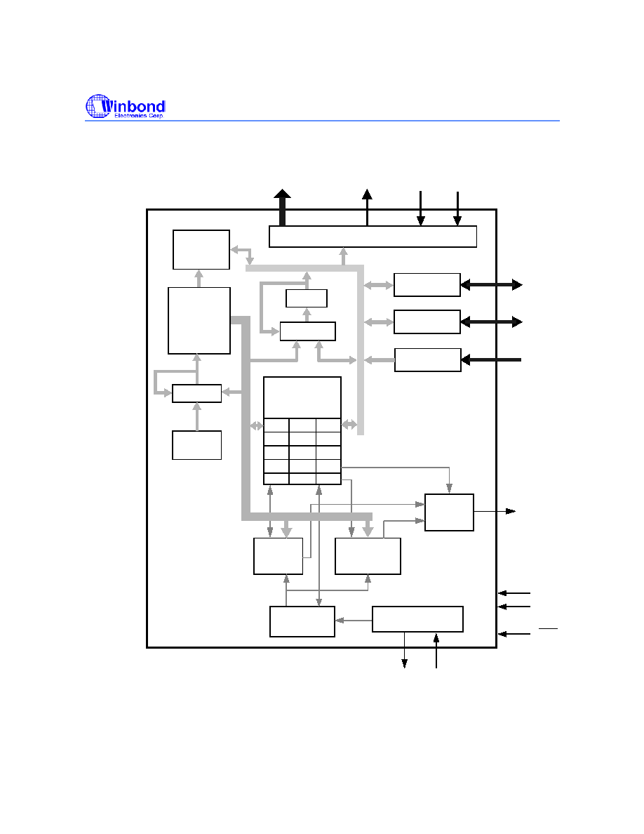
4.
BLOCK DIAGRAM ...................................................................................................................... 5
5.
PAD DESCRIPTION ................................................................................................................... 6
6.
ELECTRICAL CHARACTERISTICS........................................................................................... 7
6.1
Absolute Maximum Ratings .......................................................................................... 7
6.2
DC Characteristics ........................................................................................................ 7
6.3
AC Characteristics......................................................................................................... 8
7.
APPLICATION CIRCUIT............................................................................................................. 9
8.
REVISION HISTORY ................................................................................................................ 10

W541C240
- 2 -
1. GENERAL DESCRIPTION
The W541C240 is a high-performance 4-bit microcontroller (
�C) that provides an LCD driver.. The
device contains a 4-bit ALU, a 8-bit timers, a divider, a 24
� 4 LCD driver, and three 4-bit I/O ports.
There are also three interrupt sources and 8-level subroutine nesting for interrupt applications. The
W541C240 operates on low voltage and very low current and has two power reduction modes, hold
mode and stop mode, which help to minimize power dissipation. The W541C240 is suitable for
caculators, simple watches and clocks, multiple I/O products, keyboard controllers, speech synthesis
LSI controllers, and other products.
2. FEATURES
� Operating voltage: 2.4V to 5.5V (LCD drive voltage: 3.0V or 4.5V)
� Crystal/RC oscillation circuit selectable by code option for system clock
� Crystal oscillator: 32.768 KHz only
� RC oscillator: 1 MHz (maximum)
- High-frequency (400 KHz to 1 MHz) or low-frequency (below 400 KHz) oscillation option must
be determined by the code option.
- In RC mode, attention must be paid to the high/low frequency oscillation option, because the
LCD driver frequency is related to this option.
� Memory
- 2048 � 16 bit program ROM (shared with 2K � 4 bit look-up table)
- 64 � 4 bit data RAM (shared with 16 working registers)
- 24 � 4 LCD data RAM
� 13 input/output pins
- Ports for input only: 1 port/4 pins
- Input/output ports: 2 ports/8 pins
- MFP output pin: 1 pin (MFP)
- Do not be floating when it is as input or output open-drain (NMOS type).
� Power-down mode
- Hold function: no operation (except for oscillator)
- Stop function: no operation (including oscillator)
� Three types of interrupts
- Two internal interrupts (Divider 0, Timer 1)
- One external interrupts (Port RC)

W541C240
Publication Release Date: May 30, 2003
- 3 -
Revision A1
� LCD driver output
- 24 segment � 4 common
- Static, 1/2 duty (1/2 bias), 1/3 duty (1/2 or 1/3 bias), 1/4 duty (1/3 bias) driving mode can be
selected
� MFP output pin
- Output is software selectable as modulating or nonmodulating frequency
- Works as frequency output specified by Timer 1
� Built-in 14-bit clock frequency divider circuit
� One built-in 8-bit programmable countdown timers
- Timer 1: Offers auto-reload function and one of two internal clock frequencies (F
OSC
or F
OSC
/64)
can be selected (output through MFP pin)
� Built-in 18/14-bit watchdog timer selectable for system reset
� Powerful instruction set: 100 instructions
� 8-level subroutine (include interrupt) nesting
� Up to 4 �S instruction cycle (with 1 MHz operating frequency)
� Chip On Board available / Packaged in 64-pin QFP