 | –≠–ª–µ–∫—Ç—Ä–æ–Ω–Ω—ã–π –∫–æ–º–ø–æ–Ω–µ–Ω—Ç: W981208BH | –°–∫–∞—á–∞—Ç—å:  PDF PDF  ZIP ZIP |
W981208BH
4M
◊
4 BANKS
◊
8 BIT SDRAM
Publication Release Date: October 2000
- 1 - Revision A1
GENERAL DESCRIPTION
W981208BH is a high-speed synchronous dynamic random access memory (SDRAM), organized as
4M words
◊
4 banks
◊
8 bits. Using pipelined architecture and 0.175
µ
m process technology,
W981208BH delivers a data bandwidth of up to 143M words per second (-7). To fully comply with the
personal computer industrial standard, W981208BH is sorted into three speed grades: -7, -75 and -
8H. The -7 is compliant to the 143 MHz/CL3 or PC133/CL2 specification, the -75 is compliant to the
PC133/CL3 specification, the -8H is compliant to the PC100/CL2 specification
Accesses to the SDRAM are burst oriented. Consecutive memory location in one page can be
accessed at a burst length of 1, 2, 4, 8 or full page when a bank and row is selected by an ACTIVE
command. Column addresses are automatically generated by the SDRAM internal counter in burst
operation. Random column read is also possible by providing its address at each clock cycle. The
multiple bank nature enables interleaving among internal banks to hide the precharging time.
By having a programmable Mode Register, the system can change burst length, latency cycle,
interleave or sequential burst to maximize its performance. W981208BH is ideal for main memory in
high performance applications.
FEATURES
∑
3.3V
±
0.3V Power Supply
∑
Up to 143 MHz Clock Frequency
∑
4,194,304 Words
◊
4 banks
◊
8 bits organization
∑
Auto Refresh and Self Refresh
∑
CAS Latency: 2 and 3
∑
Burst Length: 1, 2, 4, 8, and full page
∑
Burst Read, Single Writes Mode
∑
Byte Data Controlled by DQM
∑
Power-Down Mode
∑
Auto-Precharge and Controlled Precharge
∑
4K Refresh cycles /64 mS
∑
Interface: LVTTL
∑
Packaged in TSOP II 54 pin, 400 mil - 0.80
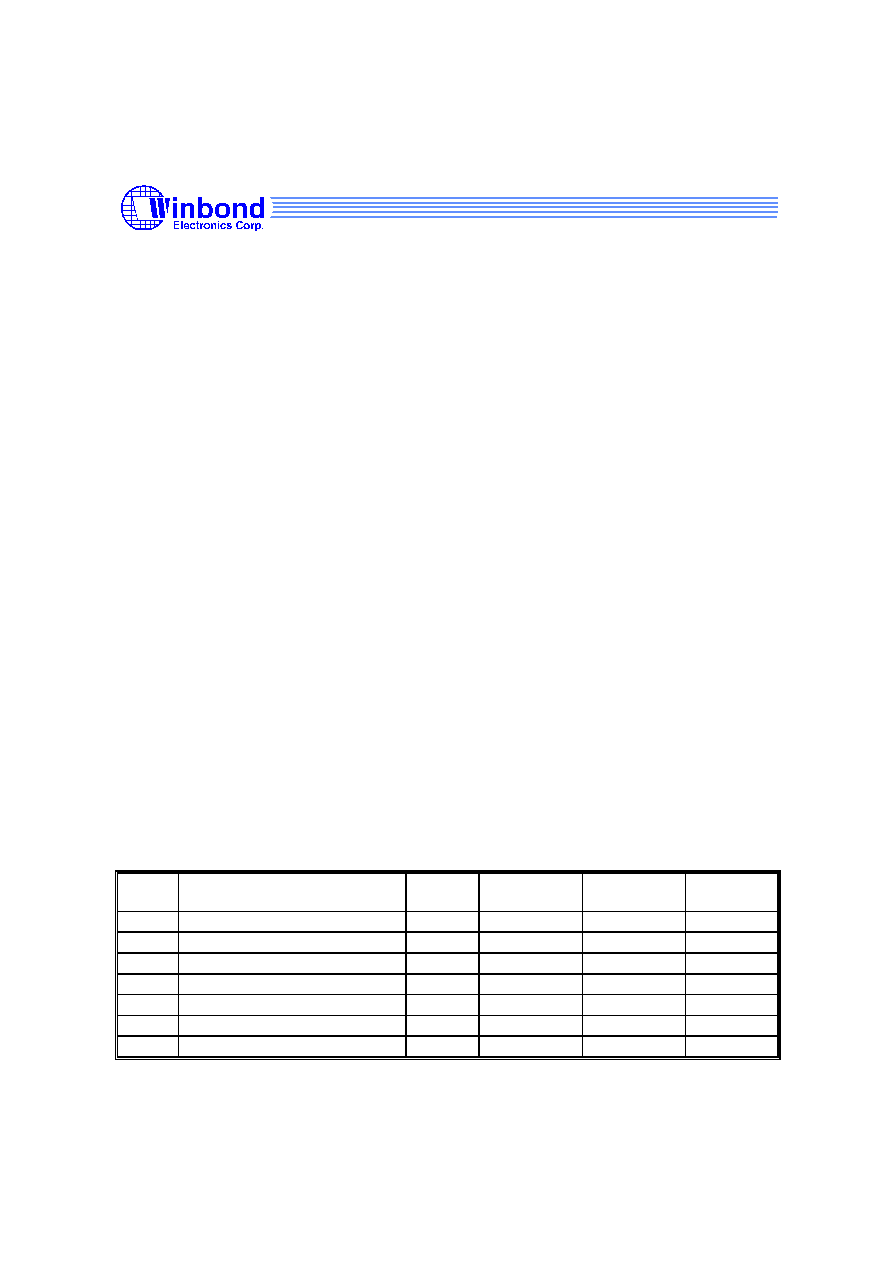
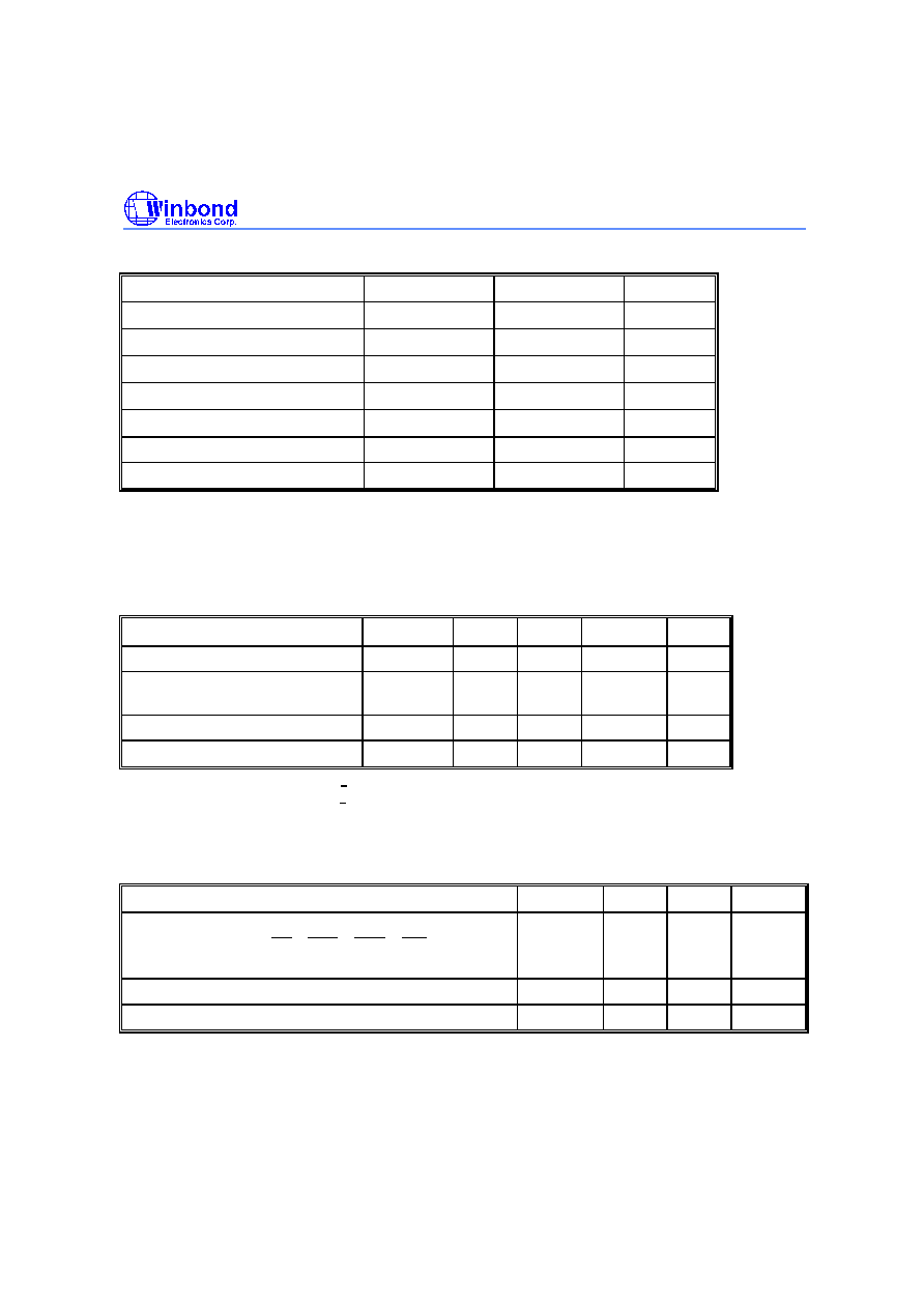
KEY PARAMETERS
SYM.
DESCRIPTION
MIN.
/MAX.
-7
(PC133, CL2)
-75
(PC133, CL3)
-8H
(PC100)
t
CK
Clock Cycle Time
Min.
7 nS
7.5 nS
8 nS
t
AC
Access Time from CLK
Max.
5.4 nS
5.4 nS
6 nS
t
RP
Precharge to Active Command
Min.
15 nS
20 nS
20 nS
t
RCD
Active to Read/Write Command
Min.
15 nS
20 nS
20 nS
I
CC1
Operation Current (Single bank)
Max.
80 mA
75 mA
70 mA
I
CC4
Burst Operation Current
Max.
100 mA
95 mA
90 mA
I
CC6
Self-refresh Current
Max.
2 mA
2 mA
2 mA
W981208BH
- 2 -
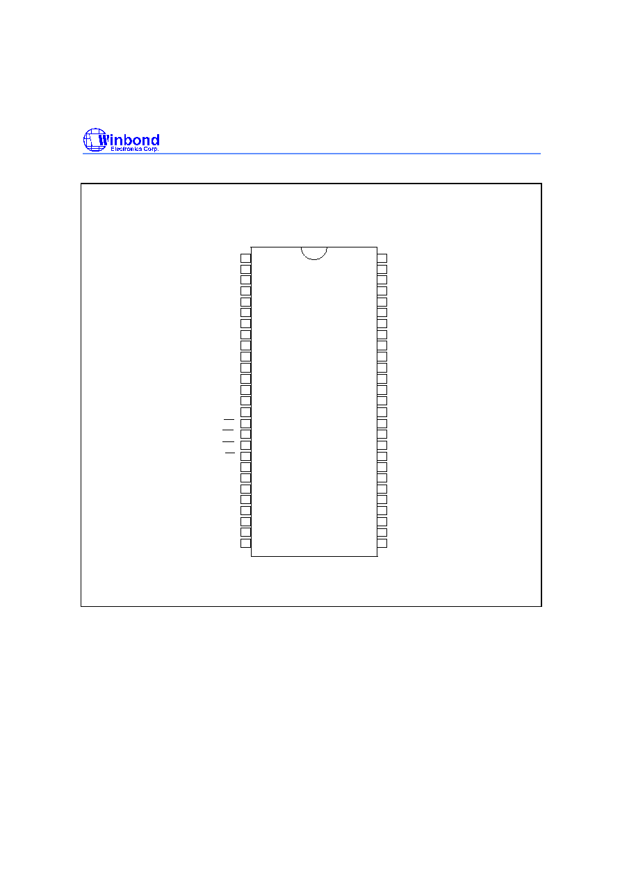
PIN CONFIGURATION
V
SS
DQ7
V
SS
Q
NC
DQ6
V
CC
Q
NC
DQ5
V
SS
Q
NC
DQ4
V
CC
Q
NC
V
SS
NC
DQM
CLK
CKE
NC
A11
A9
A8
A7
A6
A5
A4
V
SS
54
53
52
51
50
49
48
47
46
45
44
43
42
41
40
39
38
37
36
35
34
33
32
31
30
29
28
1
2
3
4
5
6
7
8
9
10
11
12
13
14
15
16
17
18
19
20
21
22
23
24
25
26
27
V
CC
DQ0
V
CC
Q
NC
DQ1
V
SS
Q
NC
DQ2
V
CC
Q
NC
DQ3
V
SS
Q
NC
V
CC
NC
BS0
BS1
A10/AP
A0
A1
A2
A3
V
CC
CS
RAS
CAS
WE
W981208BH
Publication Release Date: October 2000
- 3 - Revision A1
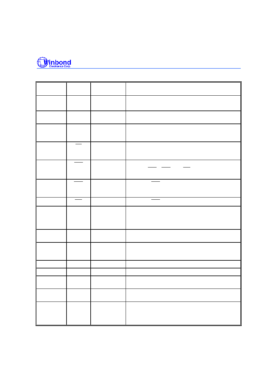
PIN DESCRIPTION
PIN NO.
PIN
NAME
FUNCTION
DESCRIPTION
23
-
26, 22,
29
-
35
A0
-
A11 Address
Multiplexed pins for row and column address.
Row address: A0
-
A11. Column address: A0
-
A9.
20, 21
BS0,
BS1
Bank Select
Select bank to activate during row address latch time,
or bank to read/write during address latch time.
2, 5, 8, 11,
44, 47, 50,
53
DQ0
-
DQ7
Data Input/
Output
Multiplexed pins for data output and input.
19
C S
Chip Select
Disable or enable the command decoder. When
command decoder is disabled, new command is
ignored and previous operation continues.
18
R A S
Row Address
Strobe
Command input. When sampled at the rising edge of
the clock, RAS , CAS and W E define the operation
to be executed.
17
C A S
Column
Address
Strobe
Referred to R A S
16
W E
Write Enable
Referred to RAS
39
DQM
Input/Output
Mask
The output buffer is placed at Hi-Z (with latency of 2)
when DQM is sampled high in read cycle. In write
cycle, sampling DQM high will block the write operation
with zero latency.
38
CLK
Clock Inputs
System clock used to sample inputs on the rising edge
of clock.
37
CKE
Clock Enable
CKE controls the clock activation and deactivation.
When CKE is low, Power Down mode, Suspend mode,
or Self Refresh mode is entered.
1, 14, 27
V
CC
Power (+3.3V)
Power for input buffers and logic circuit inside DRAM.
28, 41, 54
V
SS
Ground
Ground for input buffers and logic circuit inside DRAM.
3, 9, 43, 49
V
CC
Q
Power (+3.3V)
for I/O buffer
Separated power from V
CC
, to improve DQ noise
immunity.
6, 12, 46, 52
V
SS
Q
Ground for I/O
Buffer
Separated ground from V
SS
, to improve DQ noise
immunity.
4, 7, 10, 13,
15, 36, 40,
42, 45, 48,
51
NC
No Connection
No connection
W981208BH
- 4 -
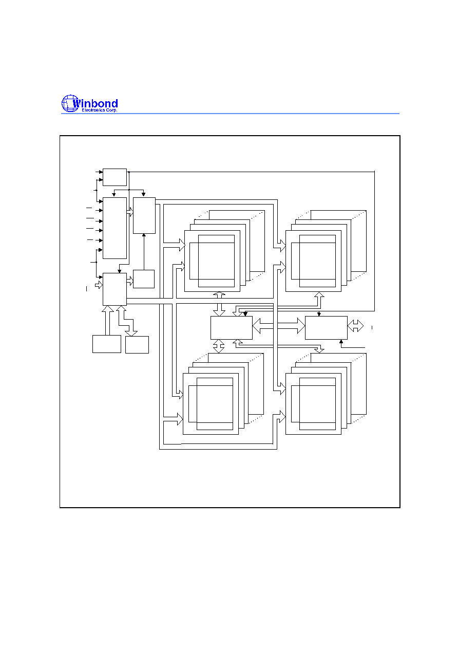
BLOCK DIAGRAM
DQ0
DQ7
D Q M
C L K
C K E
C S
R A S
C A S
W E
A 1 0
A 0
A 9
A 1 1
B S 0
B S 1
C L O C K
B U F F E R
C O M M A N D
D E C O D E R
A D D R E S S
B U F F E R
R E F R E S H
C O U N T E R
C O L U M N
C O U N T E R
C O N T R O L
S I G N A L
G E N E R A T O R
M O D E
R E G I S T E R
C O L U M N D E C O D E R
S E N S E A M P L I F I E R
C E L L A R R A Y
B A N K # 2
C O L U M N D E C O D E R
S E N S E A M P L I F I E R
C E L L A R R A Y
B A N K # 0
C O L U M N D E C O D E R
S E N S E A M P L I F I E R
C E L L A R R A Y
B A N K # 3
D A T A C O N T R O L
CIRCUIT
D Q
B U F F E R
C O L U M N D E C O D E R
S E N S E A M P L I F I E R
C E L L A R R A Y
B A N K # 1
Note: The cell array configuration is 4096 * 1024 * 8
ROW DECODER
ROW DECODER
ROW DECODER
ROW DECODER
W981208BH
Publication Release Date: October 2000
- 5 - Revision A1
ABSOLUTE MAXIMUM RATINGS
PARAMETER
SYMBOL
RATING
UNIT
Input, Output Voltage
V
IN,
V
OUT
-0.3
-
V
CC
+0.3
V
Power Supply Voltage
V
CC
, V
CCQ
-0.3
-
4.6
V
Operating Temperature
T
OPR
0
-
70
∞
C
Storage Temperature
T
STG
-55
-
150
∞
C
Soldering Temperature (10s)
T
SOLDER
260
∞
C
Power Dissipation
P
D
1
W
Short Circuit Output Current
I
OUT
50
mA
Note: Exposure to conditions beyond those listed under Absolute Maximum Ratings may adversely affect the life and reliability
of the device.
RECOMMENDED DC OPERATING CONDITIONS
(Ta = 0 to 70
∞
C)
PARAMETER
SYMBOL
MIN.
TYP.
MAX.
UNIT
Power Supply Voltage
V
CC
3.0
3.3
3.6
V
Power Supply Voltage (for I/O
Buffer)
V
CCQ
3.0
3.3
3.6
V
Input High Voltage
V
IH
2.0
-
V
CC
+0.3
V
Input Low Voltage
V
IL
-0.3
-
0.8
V
Note: V
IH
(max) = V
CC
/ V
CC
Q+1.2V for pulse width < 5 nS
V
IL
(min) = V
SS
/ V
SS
Q-1.2V for pulse width < 5 nS
CAPACITANCE
(V
CC
= 3.3V, f = 1 MHz, T
A
= 25
∞
C)
PARAMETER
SYMBOL
MIN.
MAX.
UNIT
Input Capacitance
(A0 to A11, BS0, BS1, CS , RAS , CAS , WE , DQM,
CKE)
C
I
-
3.8
pf
Input Capacitance (CLK)
C
CLK
-
3.5
pf
Input/Output capacitance
C
IO
-
6.5
pf
Note: These parameters are periodically sampled and not 100% tested.