Document Outline
- WM8581
- Multichannel CODEC with S/PDIF Transceiver
- DESCRIPTION
- FEATURES
- APPLICATIONS
- BLOCK DIAGRAM
- TABLE OF CONTENTS
- PIN CONFIGURATION
- ORDERING INFORMATION
- PIN DESCRIPTION
- ABSOLUTE MAXIMUM RATINGS
- RECOMMENDED OPERATING CONDITIONS
- ELECTRICAL CHARACTERISTICS
- TERMINOLOGY
- MASTER CLOCK TIMING
- DIGITAL AUDIO INTERFACE Ö MASTER MODE
- DIGITAL AUDIO INTERFACE Ö SLAVE MODE
- CONTROL INTERFACE TIMING Ö 3-WIRE MODE
- CONTROL INTERFACE TIMING Ö 2-WIRE MODE
- DEVICE DESCRIPTION
- INTRODUCTION
- CONTROL INTERFACE OPERATION
- DIGITAL AUDIO INTERFACES
- AUDIO DATA FORMATS
- AUDIO INTERFACE CONTROL
- DAC FEATURES
- ADC FEATURES
- DIGITAL ROUTING OPTIONS
- CLOCK SELECTION
- PHASE-LOCKED LOOPS AND S/PDIF CLOCKING (SOFTWARE MODE)
- PHASE-LOCKED LOOPS AND S/PDIF CLOCKING (HARDWARE MODE)
- S/PDIF TRANSCEIVER
- S/PDIF TRANSMITTER
- S/PDIF RECEIVER
- POWERDOWN MODES
- INTERNAL POWER ON RESET CIRCUIT
- HARDWARE CONTROL MODE
- REGISTER MAP
- DIGITAL FILTER CHARACTERISTICS
- DAC FILTER RESPONSES
- DIGITAL DE-EMPHASIS CHARACTERISTICS
- ADC FILTER RESPONSES
- ADC HIGH PASS FILTER
- RECOMMENDED EXTERNAL COMPONENTS
- PACKAGE DIMENSIONS
- IMPORTANT NOTICE
- ADDRESS:

w
WM8581
Multichannel CODEC with S/PDIF Transceiver
WOLFSON MICROELECTRONICS plc
To receive regular email updates, sign up
at
http://www.wolfsonmicro.com/enews/
Product Preview, March 2006, Rev 1.0
Copyright
2006 Wolfson Microelectronics plc
DESCRIPTION
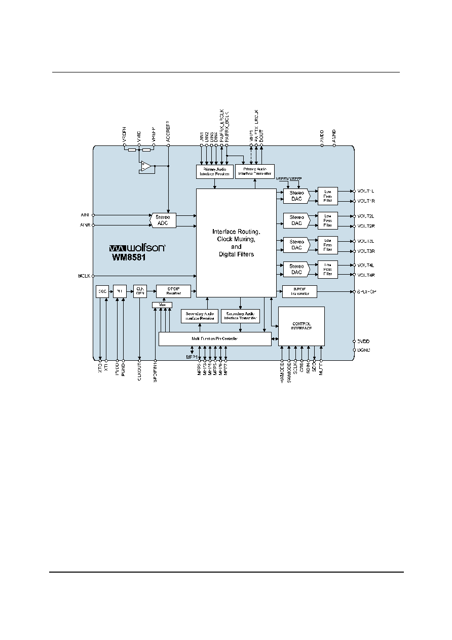
The WM8581 is a multi-channel audio CODEC with S/PDIF
transceiver. The WM8581 is ideal for DVD and surround
sound processing applications for home hi-fi, automotive
and other audiovisual equipment.
Integrated into the device is a stereo 24-bit multi-bit sigma
delta ADC with support for digital audio output word lengths
from 16-bit to 32-bit, and sampling rates from 8kHz to
192kHz.
Also included are four stereo 24-bit multi-bit sigma delta
DACs, each with a dedicated oversampling digital
interpolation filter. Digital audio input word lengths from 16-
bits to 32-bits and sampling rates from 8kHz to 192kHz are
supported. Each DAC channel has independent digital
volume and mute control.
Two independent audio data interfaces support I
2
S, Left
Justified, Right Justified and DSP digital audio formats.
Each audio interface can operate in either Master Mode or
Slave Mode.
The S/PDIF transceiver is IEC-60958-3 compatible and
supports frame rates from 32k/s to 192k/s. It has four
multiplexed inputs and one output. Status and error
monitoring is built-in and results can reported over the serial
interface or via GPO pins. S/PDIF Channel Block
configuration is also supported.
The device has two PLLs that can be configured
independently to generate two system clocks for internal or
external use.
Device control and setup is via a 2-wire or 3-wire (SPI
compatible) serial interface. The serial interface provides
access to all features including channel selection, volume
controls, mutes, de-emphasis, S/PDIF control/status, and
power management facilities. Alternatively, the device has a
Hardware Control Mode where device features can be
enabled/disabled using selected pins.
The device is available in a 48-lead TQFP package.
FEATURES
∑
Mutli-channel CODEC with 4 Stereo DACs and 1 Stereo
ADC
∑
Integrated S/PDIF / IEC-60958-3 transceiver
∑
Audio
Performance
-
103dB SNR (`A' weighted @ 48kHz) DAC
-
-90dB THD (48kHz) DAC
-
100dB SNR (`A' weighted @ 48kHz) ADC
-
-90dB THD (48kHz) ADC
∑
DAC Sampling Frequency: 8kHz ≠ 192kHz
∑
ADC Sampling Frequency: 8kHz ≠ 192kHz
∑
Independent ADC and DAC Sample Rates
∑
2 and 3-Wire Serial Control Interface with readback, or
Hardware Control Interface
∑
GPO pins allow visibility of user selected status flags
∑
Programmable Audio Data Interface Modes
-
I
2
S, Left, Right Justified or DSP
-
16/20/24/32 bit Word Lengths
∑
Four independent stereo DAC outputs with independent
digital volume controls
∑
Two Independent Master or Slave Audio Data Interfaces
∑
Flexible Digital Interface Routing with Clock Selection
Control
∑
2.7V to 5.5V Analogue, 2.7V to 3.6V Digital Supply
Operation
∑
48-lead TQFP Package
APPLICATIONS
∑
Digital
TV
∑
DVD Players and Receivers
∑
Surround Sound AV Processors and Hi-Fi systems
∑
Automotive
Audio
WM8581
Product Preview
w
PP Rev 1.0 March 2006
2
BLOCK DIAGRAM

Product Preview
WM8581
w
PP Rev 1.0 March 2006
3
TABLE OF CONTENTS
DESCRIPTION ................................................................................................................................................................................. 1
FEATURES ...................................................................................................................................................................................... 1
APPLICATIONS ............................................................................................................................................................................... 1
BLOCK DIAGRAM ........................................................................................................................................................................... 2
TABLE OF CONTENTS.................................................................................................................................................................... 3
PIN CONFIGURATION..................................................................................................................................................................... 4
ORDERING INFORMATION............................................................................................................................................................. 4
PIN DESCRIPTION .......................................................................................................................................................................... 5
MULTI-FUNCTION PINS.............................................................................................................................................................. 6
ABSOLUTE MAXIMUM RATINGS ................................................................................................................................................... 8
RECOMMENDED OPERATING CONDITIONS ................................................................................................................................ 9
ELECTRICAL CHARACTERISTICS ................................................................................................................................................. 9
TERMINOLOGY ......................................................................................................................................................................... 12
MASTER CLOCK TIMING.......................................................................................................................................................... 12
DIGITAL AUDIO INTERFACE ≠ MASTER MODE...................................................................................................................... 13
DIGITAL AUDIO INTERFACE ≠ SLAVE MODE ......................................................................................................................... 14
CONTROL INTERFACE TIMING ≠ 3-WIRE MODE ................................................................................................................... 15
CONTROL INTERFACE TIMING ≠ 2-WIRE MODE ................................................................................................................... 15
DEVICE DESCRIPTION ................................................................................................................................................................. 17
INTRODUCTION ........................................................................................................................................................................ 17
CONTROL INTERFACE OPERATION ....................................................................................................................................... 18
DIGITAL AUDIO INTERFACES.................................................................................................................................................. 22
AUDIO DATA FORMATS ........................................................................................................................................................... 24
AUDIO INTERFACE CONTROL................................................................................................................................................. 27
DAC FEATURES........................................................................................................................................................................ 30
ADC FEATURES........................................................................................................................................................................ 37
DIGITAL ROUTING OPTIONS ................................................................................................................................................... 38
CLOCK SELECTION.................................................................................................................................................................. 40
PHASE-LOCKED LOOPS AND S/PDIF CLOCKING (SOFTWARE MODE) ............................................................................... 46
PHASE-LOCKED LOOPS AND S/PDIF CLOCKING (HARDWARE MODE) .............................................................................. 53
S/PDIF TRANSCEIVER ............................................................................................................................................................. 54
S/PDIF TRANSMITTER ............................................................................................................................................................. 55
S/PDIF RECEIVER .................................................................................................................................................................... 58
POWERDOWN MODES ............................................................................................................................................................ 66
INTERNAL POWER ON RESET CIRCUIT................................................................................................................................. 67
HARDWARE CONTROL MODE ................................................................................................................................................ 70
REGISTER MAP ........................................................................................................................................................................ 73
DIGITAL FILTER CHARACTERISTICS.......................................................................................................................................... 88
DAC FILTER RESPONSES ....................................................................................................................................................... 88
DIGITAL DE-EMPHASIS CHARACTERISTICS ......................................................................................................................... 89
ADC FILTER RESPONSES ....................................................................................................................................................... 90
ADC HIGH PASS FILTER .......................................................................................................................................................... 90
RECOMMENDED EXTERNAL COMPONENTS............................................................................................................................. 91
PACKAGE DIMENSIONS............................................................................................................................................................... 93
IMPORTANT NOTICE .................................................................................................................................................................... 94
ADDRESS:................................................................................................................................................................................. 94

WM8581
Product Preview
w
PP Rev 1.0 March 2006
4
PIN CONFIGURATION
ORDERING INFORMATION
DEVICE
TEMPERATURE
RANGE
PACKAGE
MOISTURE
SENSITIVITY LEVEL
PEAK
SOLDERING
TEMPERATURE
WM8581SEFT/V
-25 to +85
o
C
48-lead TQFP
(Pb-free)
MSL1 260
∞
C
WM8581SEFT/RV
-25 to +85
o
C
48-lead TQFP
(Pb-free, tape and reel)
MSL1 260
∞
C

Product Preview
WM8581
w
PP Rev 1.0 March 2006
5
PIN DESCRIPTION
PIN NAME
TYPE
DESCRIPTION
1
VOUT4L
Analogue Output
DAC channel 4 left output
2
VOUT4R
Analogue Output
DAC channel 4 right output
3 PGND
Supply PLL
ground
4 PVDD
Supply PLL
positive
supply
5
XTI
Digital Input
Crystal or CMOS clock input
6
XTO
Digital Output
Crystal output
7
MFP7
Digital Input/Output
Multi-Function Pin (MFP) 7. See Table 1 for details of all MFP pins.
8
MFP6
Digital Input/Output
Multi-Function Pin (MFP) 6. See Table 1 for details of all MFP pins.
9
SPDIFOP
Digital Output
S/PDIF transmitter output
10
MFP5
Digital Input/Output
Multi-Function Pin (MFP) 5. See Table 1 for details of all MFP pins.
11
MFP4
Digital Input/Output
Multi-Function Pin (MFP) 4. See Table 1 for details of all MFP pins.
12
MFP3
Digital Input/Output
Multi-Function Pin (MFP) 3. See Table 1 for details of all MFP pins.
13
SPDIFIN1
Digital Input
S/PDIF Receiver Input 1
14
CLKOUT
Digital Output
PLL or crystal oscillator clock output
15 DVDD
Supply Digital
positive
supply
16 DGND
Supply Digital
ground
17
MUTE
Digital Input/Output
DAC mute-all input/ All-DAC Infinite Zero Detect (IZD) flag output
18
DIN1
Digital Input
Primary Audio Interface (PAIF) receiver data input 1
19
DIN2
Digital Input
Primary Audio Interface (PAIF) receiver data input 2
20
DIN3
Digital Input
Primary Audio Interface (PAIF) receiver data input 3
21
DIN4
Digital Input
Primary Audio Interface (PAIF) receiver data input 4
22
PAIFRX_LRCLK
Digital Input/Output
Primary Audio Interface (PAIF) receiver left/right word clock
23
PAIFRX_BCLK
Digital Input/Output
Primary Audio Interface (PAIF) receiver bit clock
24
MCLK
Digital Input/Output
System Master clock; 256, 384, 512, 768, 1024 or 1152 fs
25
DOUT
Digital Output
Primary Audio Interface (PAIF) transmitter data output
26
PAIFTX_LRCLK
Digital Input/Output
Primary audio interface transmitter left/right word clock
27
MFP1
Digital Input/Output
Multi-Function Pin (MFP) 1. See Table 1 for details of all MFP pins.
28
MFP2
Digital Input/Output
Multi-Function Pin (MFP) 2. See Table 1 for details of all MFP pins.
29
HWMODE
Digital Input
Configures control to be either Software Mode or Hardware Mode
30
SWMODE
Digital Input/Output
Configures software interface to be either 2-wire or 3-wire. See note 2.
31
SDO
Digital Output
3-wire control interface data output. See note 3.
32
SDIN
Digital Input/Output
Control interface data input (and output under 2-wire control)
33
SCLK
Digital Input
Control interface clock
34
CSB
Digital Input
3-wire control interface latch signal / device address selection
35
AINR
Analogue Input
ADC Right Channel Input
36
AINL
Analogue Input
ADC Left Channel Input
37
ADCREFP
Analogue Output
ADC reference buffer decoupling pin; 10uF external decoupling
38
VMID
Analogue Output
Midrail divider decoupling pin; 10uF external decoupling
39 AGND
Supply Analogue
ground
40 AVDD
Supply Analogue
positive
supply
41
VOUT1L
Analogue Output
DAC channel 1 left output
42
VOUT1R
Analogue Output
DAC channel 1 right output
43
VOUT2L
Analogue Output
DAC channel 2 left output
44
VOUT2R
Analogue Output
DAC channel 2 right output
45
VREFP
Analogue Input
DAC and ADC positive reference
46
VREFN
Analogue Input
DAC and ADC ground reference