DAA with 2/4 Wire Hybrid
XE0002B
Features
∑ Small Size - 1.25" x 1.0" x 0.5"
∑ FCC Part 68 Compliant
∑ Ring Detection
∑ 2 to 4 Wire Converter
∑ 1500 Volt Isolation
∑ 800 Volt Surge Protection
∑ Hookswitch Control
Description
The XE0002B Data Access Arrangement provides a
'direct connect' telephone line interface. It complies
with FCC Part 68 hazardous voltage, surge and leakage
current specifications. This component may be used as
the direct connect telephone line interface for virtually
any application in which voice or data is to be
transmitted over the public switched telephone network.
The XE0002B provides high voltage isolation,
independent on/off hook control, ring detection circuitry
and a 2 to 4 wire converter hybrid for use in modem
applications. It operated from ±5 volt power supplies
and occupies 1.25 square inches of board space.
1 ∑
20
2
3
4
17
5
6
7
14
8
13
9
12
10
11
V
DD
Vcc
RI
RCVR
XMIT
XMFR
T1
OH
GND
T2
TIP
RING
N/C
N/C
N/C
N/C
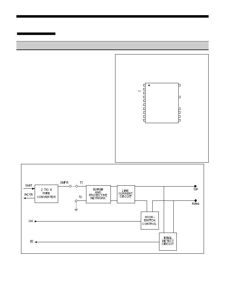
PIN CONFIGURATION
C A U T I O N
PINS 17 & 20 HAVE 1500V ISOLATION FROM THE REST OF
THE CIRCUITRY. THIS ISOLATION SHOULD BE
PRESERVED THROUGHOUT THE SYSTEM
XECOM
(Top View)
Block Diagram
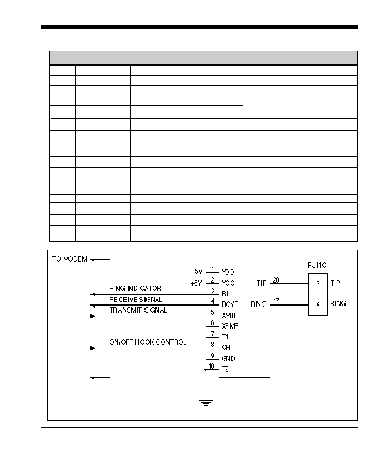
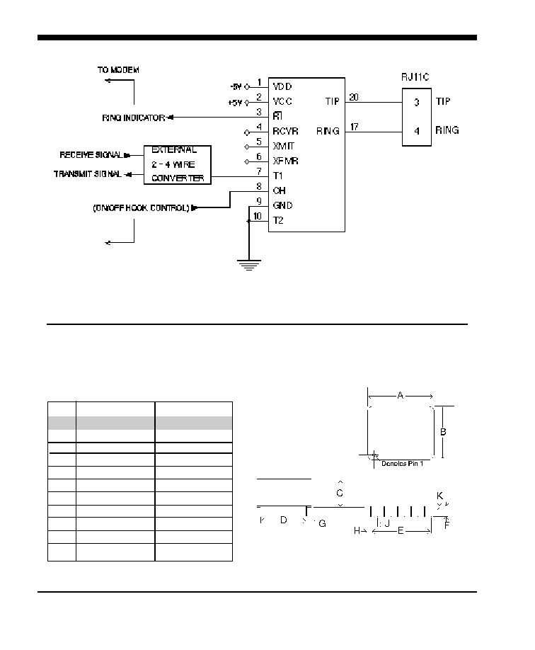
Typical Connection Diagram
2/XECOM
XE0002B
PIN NAME
I/O
DESCRIPTION
Pin Descriptions
1
VDD
---
-5 Volts.
2
VCC
---
+5 Volts
3
\RI
O
Ring Indicator, output, active LO, TTL. When low indicates the
modem is receiving a ring signal.
4
RCVR
O
Analog signal output from the 2-4 wire convertor.
5
XMIT
I
Analog signal input to the 2-4 wire convertor.
6
XMFR
I
Analog input/output from the Surge and Protective Network to the
internal 2-4 wire convertor. Must be tied to pin 7, T1, to use the
internal 2-4 wire convertor.
7
T1
I
Analog Signal input/output to the Surge and Protective network.
8
OH
I
Off-Hook controls the hookswitch relay within the XE0002B. A high
on OH closes the internal relay and connects the equipment to the
telephone line.
9
GND
---
Ground.
10
T2
I
Analog Signal input/output to the Surge and Protective network.
17
RING
---
Ring connection to the phone line (RJ11 pin4) from the internal DAA.
20
TIP
---
Tip connection to the phone line (RJ11 pin3) from the internal DAA.
4/XECOM
XE0002B
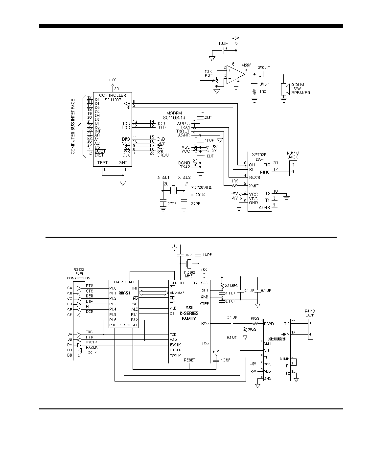
1200bps Modem Using Sierra Semiconductor SC11007/SC11014
Typical Connection Diagram with Silicon Systems K-Series Family