xecom
2400bps Serial Input Component Modem
XE2401L
02-13-96
Description
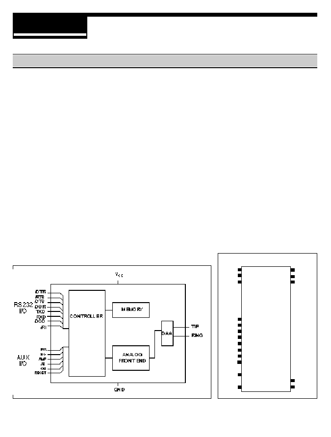
Xecom's XE2401L component modem is a
complete 2400 bps data modem. Its
compact size and TTL level, serial interface
allows for quick integration into virtually any
new or existing design. The XE2401L
contains all of the circuitry required for
complete modem operation, including a user
transferable FCC Part 68 registration,
allowing direct connection to the Telephone
Network. The XE2401L was specifically
designed to provide industrial systems
manufacturers with a complete, highly
integrated, compact solution for adding data
communication to their products.
Block Diagram
1
40
2
39
3
38
9
10
11
12
13
14
15
16
18
22
20
21
Reset
AR
RXD
DTR\
AA\
CTS\
OH
TXD
RTS\
HS\
RI\
TIP
RING
+5V
\DSR
\DCD
AMP
GND
PIN CONFIGURATION
Features
� Small Size 1.08" x 2.28" x 0.42",
� FCC Part 68 Registered, user transferable
� Data Transfer at 2400, 1200 and 300 bps
� Supported Protocols:
- CCITT V.22bis, V.22, V.21
- Bell 212A, 103
� TTL serial interface interfaces with
industry standard UART's
� Single +5v supply
� Modem control with Industry standard "AT"
command set
� Standard package allows easy upgrades
to Fax (XE9624F) and 9600 bps (XE9601)
operation
(Top View)
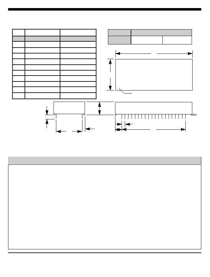
Mechanical Specifications - Package type 'C2'
2/XECOM
XE2401L
PIN NAME
I/O
DESCRIPTION
1
RESET
I
External reset pin active HI, TTL. An internal circuit resets the modem
when power is applied, no external reset is required. Any external reset
applied to the modem must be applied for a minimum of 100
milliseconds.
2
AR
O
Auxiliary Data/Voice Relay output, active HI, TTL/CMOS. When high the
external, auxiliary telephone set relay is closed and the modem is in the
voice mode.
3
RXD
O
Serial data output to the DTE (i.e. external UART). A logic "high"
represents a "mark" and a logic "low" represents a "space", TTL.
9
\DTR
I
Data Terminal Ready, input, active LO, TTL. The function of this pin
is set by the &D command and the value in register S21.
Pin Descriptions
A
C
F
G
H
J
PIN 1 DOT
E
K
D
B
�
Pins: 0.025" x 0.025"
All pins tin-plated
Recommended hole
size: 0.056"
INCHES
METRIC(MM)
PIN
MIN
MAX
MIN
MAX
A
2.270
2.290
57.66
58.17
B
1.070
1.090
27.18
27.69
C
0.420
0.430
10.67
10.92
D
0.890
0.910
22.61
23.11
E
1.890
1.910
48.01
48.51
F
0.125
0.200
03.18
05.08
G
0.080
0.100
02.03
02.54
H
0.180
0.200
04.57
05.08
J
0.090
0.110
02.29
02.79
K
0.020
0.025
00.51
00.64
WEIGHT
METRIC
ENGLISH
31.75 grams
1.12 oz.

XE2401L
XECOM\3
Note: No other pin positions are present, i.e. only 18 physical pins are on this device.
No pins are present at positions 4, 5, 6, 7, 8, 17, 19, 23 - 37
10
\AA
O
Auto Answer enable indicator, output, active LO, TTL/CMOS.
11
\CTS
O
Clear to Send, output, active LO, TTL/CMOS. A low indicates the
modem is ready to accept data signals for transmission.
12
OH
O
Off-Hook, output, active HI, TTL/CMOS. A high indicates the modem's
hookswitch relay is closed connecting the modem to the telephone line.
13
TXD
I
Serial data input from the DTE (i.e. external UART). A logic "high"
represents a "mark" and a low represents a"space", TTL.
14
\RTS
I
Request to Send, input, active LO, TTL.
15
HS
O
High Speed indicator, output, active LO, TTL/CMOS. Low when
operating at 2400bps rate, high otherwise.
16
\RI
O
Ring Indicator, output, active LO, TTL. When low indicates the
modem is receiving a ring signal.
18
TIP
---
Tip connection to the phone line (RJ11 pin3) from the internal DAA.
20
RING
---
Ring connection to the phone line (RJ11 pin4) from the internal DAA.
Caution: Observe design rules for Tip & Ring trace layout.
21
GND
---
Ground.
22
AMP
---
Audio output to speaker. Function is determined by L & M commands
and the value in register S22. The imput impdedence to the speaker
driver must be greater tha 300 ohms.
38
\DCD
O
Data Carrier Detect, output, active LO, TTL/CMOS. Function is set by
the &C command and the value in register S21.
39
\DSR
O
Data Set Ready, output, active LO, TTL/CMOS. Function is set by the
&S command and the value in register S21.
40
Vcc
---
+5 Volts.
PIN NAME
I/O
DESCRIPTION

4/XECOM
XE2401L
AT Commands
The XE2401L uses "AT" commands for
configuration and control. This section describes
use of the AT command format and lists the AT
commands, Registers and Result codes.
Modes of Operation
The "AT" commands have two operational
modes; Command Mode and Data Mode.
Data Mode: The XE2401L enters data mode
after it connects with a remote modem and issues
an appropriate "CONNECT" result code. In the
Data Mode the modem sends all data presented
on Transmit Data (TXD) to the remote modem
and puts data from the remote modem onto
Received Data (RXD). When the modem exits
data mode, it issues a "NO CARRIER" result
code.
Command Mode: The XE2401L enters
command mode on power-up, reset, a lost
connection, or receipt of the escape code. In
command mode the modem accepts commands
from the host on transmit data. Appropriate result
codes are returned on received data.
Command Line Format
Command lines issued to the modem follow a
strict format. Each command begins with the
prefix AT. The command line is stored in the
command buffer and executed upon receipt of a
carriage return. Until executed, the command
line can be editied with the backspace key.
Command Prefix - Each command, except the
A/ command, begins with the AT prefix. The "A"
and "T" may be either both upper case or both
lower case but cannot be of different cases. The
prefix identifies the speed and parity of the
commands sent to the modem by the host.
Speed is determined by measuring the width of
the incoming bits. Parity is determined by
comparing the parity bit of the "A" and the "T."
Command Line - Commands may be strung
together in a single command line of up to 40
characters. Commands are executed in the
sequence they appear. Spaces may be inserted
into the command line but do not fill space in the
command buffer. A carriage return terminates the
command line and causes the commands to be
executed. Register S3 allows the user to select a
character other than a carriage return to terminate
the command line.
Command Buffer - No more than 40 characters,
including the AT prefix, may be loaded into the
command buffer. If the command buffer
overflows, the modem issues an "ERROR" result
code and commands are not executed.
Command Line Editing - The backspace can be
used to edit a command line before it is executed.
The backspace key, (Control and H
simultaneously on some systems), erases the
previous character in the command line. Register
S5 allows the user to select a character other
than a backspace to edit the command line.
Re-Execute Last Command - The A/ command
causes the modem to reexecute the last
command line. This is the only command which
does not require the "AT" prefix.
Ommitted Parameters - Most commands include
a parameter which determines how the functions
will be set. When the command parameter is
omitted from the command string, it is assumed to
be a 0.

XE2401L
XECOM\5
The XE2401L uses "AT" commands for
configuration and control. This section describes
use of the AT command format and lists the AT
commands, Registers and Result codes.
Modes of Operation
The "AT" commands have two operational
modes; Command Mode and Data Mode.
Data Mode: The XE2401L enters data mode
after it connects with a remote modem and issues
an appropriate "CONNECT" result code. In the
Data Mode the modem sends all data presented
on Transmit Data (TXD) to the remote modem
and puts data from the remote modem onto
Received Data (RXD). When the modem exits
data mode, it issues a "NO CARRIER" result
code.
AT Command List
An asterisk indicates the factory default
A - Answer Command -
Bn - Select Communications Standard
n=0
Selects CCITT standards
n=1
Selects Bell standards*
D - Dial Command -
P =
Pulse dial
T =
Tone dial
R =
Connect as an answering modem
W =
Wait for dial tone
, =
Pause for the duration of S8
@ =
Wait for silence
! =
Switch hook flash
; =
Return to the command state
En - Command Echo
n=0
Do not echo commands
n=1
Enable command echo*
Hn - Switch Hook Control -
n=0 Switch hook relay closes*
n=1 The switch hook relay opens
In - Modem Identification
Ln - Speaker Volume -
n=0
Low speaker volume
n=1
Low speaker volume
n=2
Moderate speaker volume*
n=3
High speaker volume
Mn - Speaker Activity -
n=0
Speaker off
n=1
Speaker on until carrier received*
n=2
Speaker remains on
n=3
Speaker on after dialing until carrier is
detected.
On - On Line
n=0
Return On Line with no retrain*
n=1
Initiate retrain while returning On line.
Qn - Responses
n=0
Send responses *
n=1
No Responses
Sr? - Interogate Register -
Sr=n - Set Register Value -
Vn - Result Codes -
n=0
Numeric Result Codes
n=1
English Word Result Codes*
Xn - Result Code Set -
n=0
Responses 0-4*
n=1
Responses 0-5 & 10
n=2
Responses 0-6 & 10
n=3
Responses 0-5, 7 & 10
n=4
Responses 0-7 & 10
Yn - Long Space Disconnect -
n=0
Disabled *
n=1
Enabled