
XECOM
(1)
XE900S
XE900S
November 2003
XE900S Smart Spread Spectrum Transceiver
Description
The XE900S combines a spread spectrum transceiver
and micro-controller into a single easy-to-use, FCC Part
15 Registered module. The embedded communications
controller manages the Frequency Hopping Spread
Spectrum (FHSS) link and the host system interface.
The XE900S supports two unique features to simplify
wireless networking. Count-Off allows the network
master to retrieve the status of 253 remote nodes in less
than 10 seconds with a single broadcast command.
SensorOnAir
TM
eliminates the need for an application
micro-controller by utilizing the communications
controller to directly manage analog inputs and digital
control lines.
Xecom has two XE900S models. XE900S-10 supports a
power output range of 0 to 10 mW; XE900S-500 has a
power output range of 100 to 500 mW. The XE900S-10
costs less and uses less power; the XE900S-500 has
greater range and signal penetration.
Features
* Small Size: 1.295" by 1.410" by 0.255"
* Serial Control and Configuration of the Wireless Link.
* Supports a 254 node point-to-multipoint network
* Programmable Transmit Power Output.
XE900S-10 - 0 to 10 mW;
XE900S-500 - 100 to 500 mW.
* Typical Receiver Sensitivity -100 dBm
* Obstructed signal range to 1500 feet (XE900S-500);
* Wireless Data Rate 76.8K bps, half-duplex
* Low power Consumption
XE900S-10: 50 mA @ 3.3 Volts; 1 mW output power
XE900S-500: 100 mA @ 3.3 Volts; 100 mW output
power
* SensorOnAir
TM
allows direct connection of sensors to
the Smart Transceiver
* Count Off allows the host node to download the
status of all nodes in under 10 seconds.
* Operating Temperature Range of -40 to +85 C
* FCC Part 15 Registered
XE900S Block Diagram
Analog
Inputs
Antenna
MUX
AMP
COMM.
CONTROLLER
ROM
Serial I/F
Digital I/O
TRANSCEIVER
SAW
FILTER
SAW
FILTER
Preliminary
XECOM
(2)
XE900S
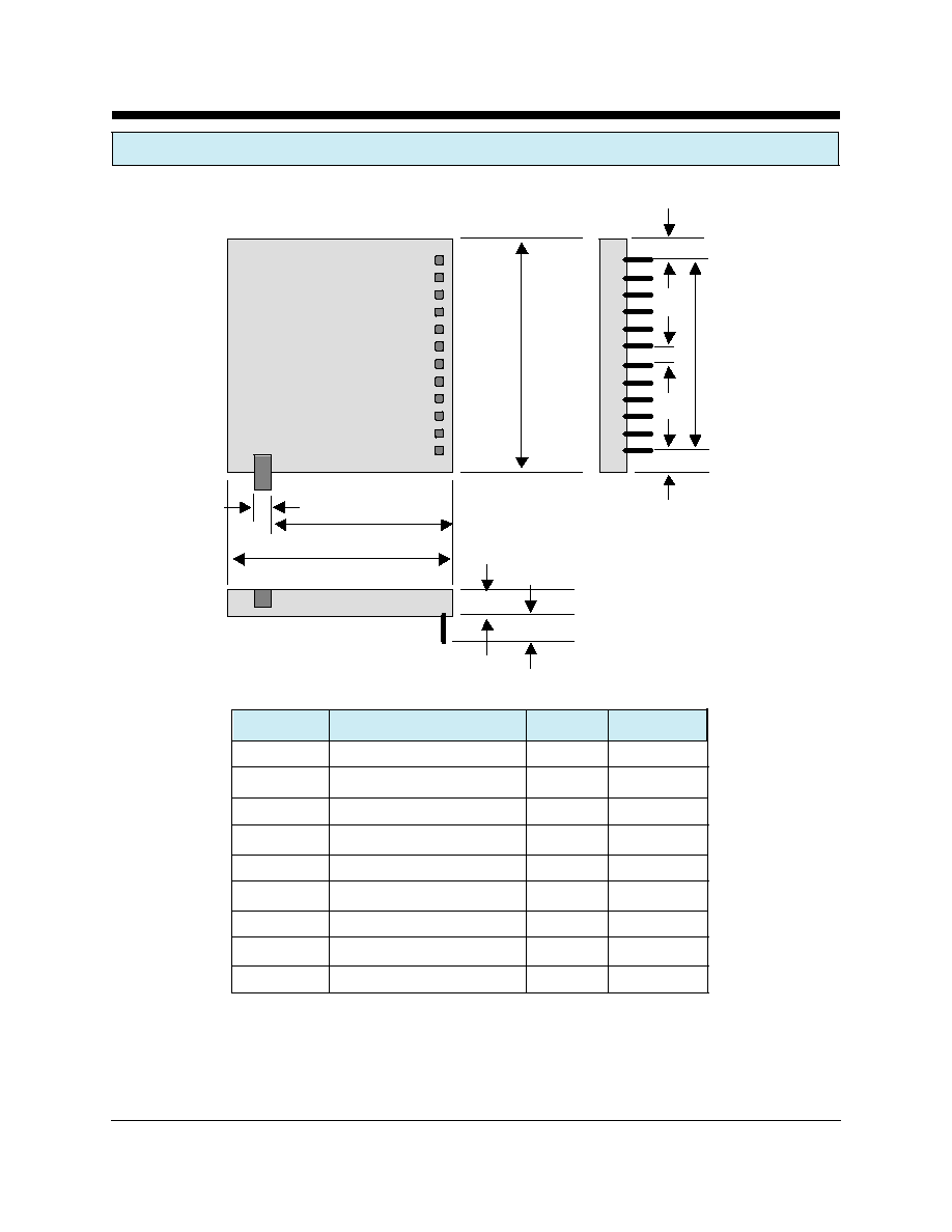
XE900S MECHANICAL SPECIFICATIONS
A
B
C
D
E
I
G
H
H
F
Top View
Dimension Description
Inches
MM
A
Module Width
1.295
32.89
B
Module Length
1.410
35.81
C
Module Thickness
0.255
6.48
D
Minimum Lead Length
0.100
2.54
E
Antenna Width
0.134
3.40
F
Edge to Antenna
0.995
25.27
G
Pin to Pin Spacing
0.100
2.54
H
Edge to End of Pin Row
0.155
3.94
I
Pin Row Length
1.100
27.94
XECOM
(3)
XE900S
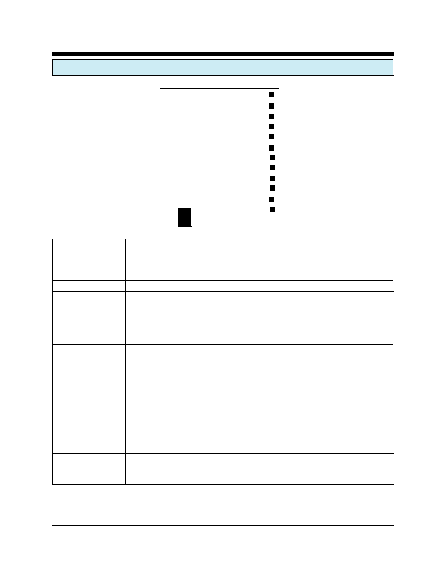
XE900S PIN CONFIGURATION
12
ADC0
11
ADC1
10
DIO0
9
DIO1
8
DIO2
7
DIO3
6
/RTS
5
/CTS
4
/RXD
3
/TXD
2
VCC
1
GND
SIGNAL
PINS
DESCRIPTION
Ground
1
Common voltage reference for the XE900S.
VCC
2
3.3 Volt power for the XE900S.
/TXD
3
Transmit Data is the data input to the XE900S
/RXD
4
Received Data is the data output from the XE900S.
/CTS
5
Clear to Send provides hardware flow control from the XE900S. The XE900S drives /CTS
high to signal the host to temporarily stop the flow of data on the /TXD.
/RTS
6
Request to Send provides hardware flow control from the host system. The host system
drives /RTS high to signal the XE900S to temporarily stop the flow of data on /RXD.
DIO3
7
DIO0 may be programmed as either a digital input or digital output. It connects directly to
the communications controller in the XE900S.
DIO2
8
DIO2 may be programmed as either a digital input or digital output. It connects directly to
the communications controller in the XE900S.
DIO1
9
DIO1 may be programmed as either a digital input or digital output. It connects directly to
the communications controller in the XE900S.
DIO0
10
DIO0 may be programmed as either a digital input or digital output. It connects directly to
the communications controller in the XE900S.
ADC1
11
Analog Input 1 to the XE900S' communications controller. ADC1 connects to an internal
10-bit Analog to Digital Convertor. ADC0 may also be configured as a digital input if no
analog inputs are required. DIO0
ADC0
12
Analog Input 0 to the XE900S' communications controller. ADC0 connects to an internal
10-bit Analog to Digital Convertor. ADC0 may also be configured as a digital input if no
analog inputs are required.
XE900S
Top View

XECOM
(4)
XE900S
ABSOLUTE MAXIMUM RATINGS
VCC
3.9 Volts
Storage Temperature
-55
O
C to +125
O
C
Operating Temperature Range
-40
O
C to +85
O
C
WARNING: Exceeding any of these ratings will void the warranty and may damage the device
XE900S ELECTRICAL SPECIFICATIONS
VCC
2.7
3.3
3.6
Volts
Transceiver power
ICC
XE900S-10
50
mA
Transmit Mode (1 mW output)
XE900S-500
100
mA
Transmit Mode (100 mW output)
All
30
mA
Receive Mode
All
15
mA
Idle Mode
All
10
uA
Sleep Mode
Output Power: XE900S-10
1
10
mW
50 Ohm Load
XE900S-500
100
500
mW
50 Ohm Load
Wireless Receive Sensitivity
-100
dBm
76.8K bps
Range thru Physical Obstructions
1500
XE900S-500, 76,800 bps
Frequency Hopping Channels
63
Frequency Band
902
928
MHz
Antenna Output Impedance
50
Ohms
Latency
TBD
mSec
Voh
2.25
Volts
VCC =3.3 Volts
Vol
0.75
Volts
VCC =3.3 Volts
Vih
2.25
Volts
VCC =3.3 Volts
Vil
0.75
Volts
VCC =3.3 Volts
Parameter
Min
Typ
Max
Units
Comments

XECOM
(5)
XE900S
XE900S TYPICAL CONNECTION DIAGRAM
GND
VCC
/RXD
/TXD
/CTS
/RTS
DIO3
DIO2
DIO1
DIO0
ADC1
ADC0
Antenna
Host
Serial
I/F
3.3V
C1 C2 C3 C4 C5
L1
Parts List for XE900S Typical Connection Diagram
Reference
Designation
Qty
Description
C1
1
Capacitor, Electrolytic, 100 ufd, 10 Volts
C2, C4
2
Capacitor 0.1 ufd, 10Volts
C3, C5
2
Capacitor 47 pfd, 10 Volts
L1
1
Coilcraft 0603HC-7N5XJB
Antenna *
1
50 Ohm, 1/4 Wave;
* The Antenna connector on teh XE900S is a Male MMCX connector.
An femle MMCZ to Female SMA adapter will be need for the antenna
connection