XECOM
(1)
XE924M
XE924M
March 2003
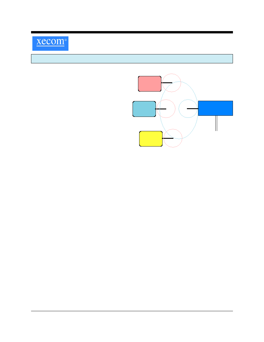
XE924M Base Access Point for Multiple Remote Machines
Description
Xecom combines proven embedded modem technology
and a 900 MHz transceiver in the XE924M, Base Access
Point. The Base Access Point is a simple scheme to
connect up to 128 remote systems to a single dial-up
telephone line. Each remote system communicates with
the Base Access Point using Xecom's XE900M Smart
Transceiver. The XE924M eliminates hardware
redundancy, and therefore reduces both the initial
investment and operating costs.
Xecom's Base Access Network significantly reduces
hardware costs in locations with multiple systems. For
example, credit card verification normally requires a
dedicated modem and telephone line for each sales
terminal. Each time a terminal is added another modem
and another telephone line also need to be added. The
Base Access Point connects all of the terminals through
one shared modem and telephone line. The only
hardware requirement is the addition of an XE900M
Smart Transceiver to the terminal equipment.
This scheme eliminates the installation requirements of
a wired network. Whether you add a system equipped
with a Smart Transceiver to the network or build a new
facility, the 900 MHz wireless link eliminates the need to
install cables and configure a server. By virtue of its
commonality with millions of cordless telephones the
XE924M also offers the most cost effective wireless
link available.
The XE924M reduces hardware costs in multiple
system environments. Systems which now require a
dedicated modem and telephone line for each unit
can be connected through the shared modem and
telephone line.
Features
* Small Size: 2.75" by 1.38: by 0.500"
* Provides dial-up network access for up to 128
machines equipped with Xecom's XE900M Smart
Transceiver.
* Count-off feature allows polling of all 128 nodes in
less than 5 seconds
* Telephone Modem Data Transfer at 300, 1200, and
2400 BPS
* Telephone Modem Control and Configuration via
industry standard AT Commands.
* Supports 126 Wireless Carrier Frequency from 902 to
928 MHz
* Wireless Range; maximum 150 Feet indoors
* Wireless Data Rate 9600 BPS, half-duplex
* Integrated communications controller regulates the
wireless communications protocols, error correction
and controls the wireless link to the modem.
* In circuit upgradeable firmware
* User Transferrable FCC Part 68 Registration
* FCC Part 15 Compliance
Preliminary
System A
XE900M
Equipped
XE924M
Base Access
Point
Dial-up
Telephone
Line
System B
XE900M
Equipped
System C
XE900M
Equipped
900MHz Base Access Network
XECOM
(2)
XE924M
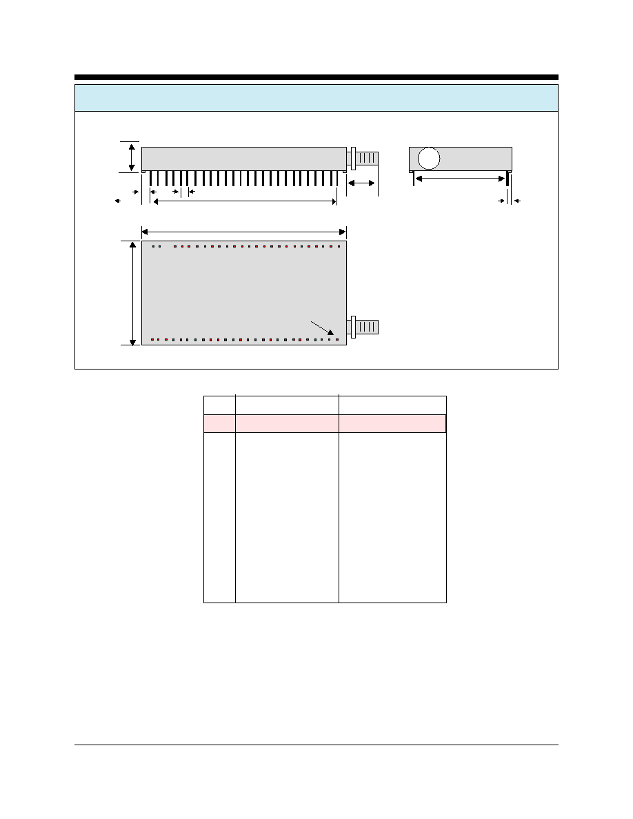
XE924M MECHANICAL SPECIFICATIONS
Inches
MM
PIN
MIN
MAX
MIN
MAX
A
2.740
2.760
69.60
70.10
B
0.500
0.520
12.70
13.21
C
1.370
1.390
34.80
35.31
D
5.300
0.510
13.46
12.95
E
2.490
2.510
63.25
63.37
F
0.090
0.110
2.29
2.79
G
0.115
0.135
2.92
3.43
H
1.190
1.210
30.23
30.73
J
0.130
0.150
3.30
3.81
Pin Description:
Pins are gold plated
Pin Dimensions .025 inches square, .minimum 0.120 inches long
A
B
C
D
E
F
G
H
J
(Top View)
Pin 1
XECOM
(3)
XE924M
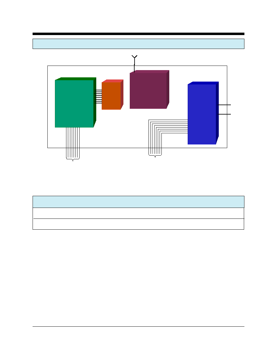
XE924M BLOCK DIAGRAM
Comm
Controller
FLASH
2400 BPS
MODEM
Tip
Ring
900 MHz
Transceiver
Antenna
Modem
Serial IF
Communications
Controller
Serial IF
ABSOLUTE MAXIMUM RATINGS
Storage Temperature
-25
O
C to +85
O
C
Operating Temperature Range
1
0
O
C to +70
O
C
1
Units may be screened for operation from -40 to +85C. An extra charge will be applied for this screening.
XECOM
(4)
XE924M
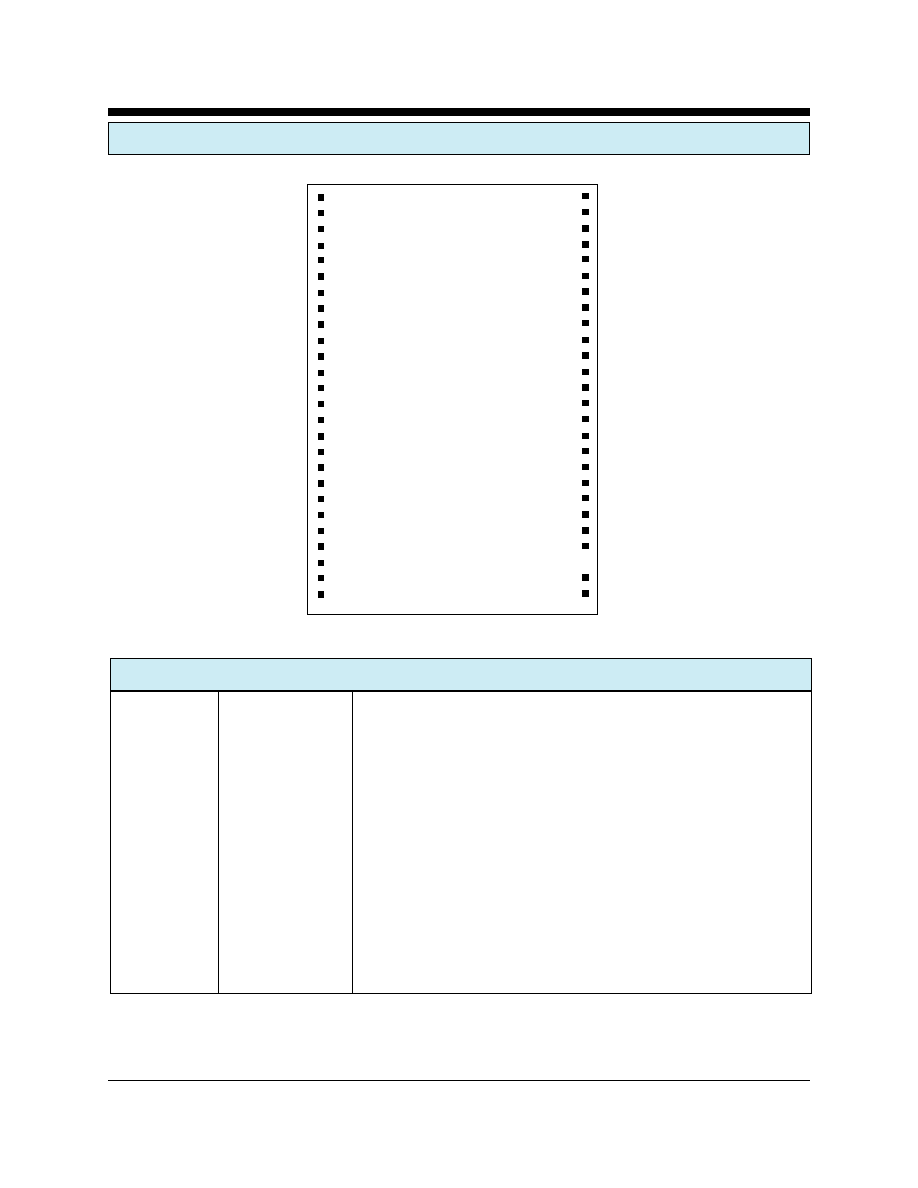
XE924M PIN CONFIGURATION
XE924M PIN CONFIGURATION
SIGNAL
PINS
DESCRIPTION
RGND
1, 3, 5, 7, 9, 39,
RFGND provides the common reference point for all high frequency
43, 44, 46, 48, 50, 52
signals.
RESERVED
2, 4, 6, 8, 11, 12, 13,
These pins are reserved for future use. No connections should be
18, 40,41, 42, 45, 47,
should be made to these pins.
49, 51
VDD
14
VDD provides 3 volt power to the communications controller
DGND
15
DGND provides the ground reference for the modem and
communications controller circuitry in the XE924M.
/RST_VPP
16
RST_PV provides a hardware reset line for the XE924M's
communications controller.
VCC
17
VCC provides 3 volt power to the 900 MHz transceiver
1
2
3
4
5
6
7
8
9
10
11
12
13
14
15
16
17
18
19
20
21
22
23
24
25
26
52
51
50
49
48
47
46
45
44
43
42
41
40
39
38
37
36
35
34
33
32
31
30
28
27
XE924M
RGND
RESERVED
RGND
RESERVED
RGND
RESERVED
RGND
RESERVED
RGND
RGND
RESERVED
RESERVED
RESERVED
VDD
DGND
/RST_VPP
VCC
RESERVED
/DSR
/MDM_DSR
RXD
/MDM_RXD
TXD
/MDM_TXD
/RI
/MDM_RI
RGND
RESERVED
RGND
RESERVED
RGND
RESERVED
RGND
RESERVED
RGND
RGND
RESERVED
RESERVED
RESERVED
RGND
/CTS
/MDM_CTS
/DCD
/MDM_DCD
/DTR
/MDM_DTR
/RTS
/MRTS
Vmd
TIP
RING
XECOM
(5)
XE924M
XE924M PIN CONFIGURATION
SIGNAL
PINS
DESCRIPTION
/DSR
19
/DSR is the Data Set Ready input to the communications controller. This
pin is normally tied to /MDSR, pin 20
/MDSR
20
/MDSR supplies the Data Set Ready output from the modem. /MDSR is
an active low output. This pin is normally tied to /DSR, pin 19.
RXD
21
RXD is the serial data input to the communications controller. This pin is
normally tied to /MRXD, pin 22.
/MRXD
22
/MRXD is the serial data output from the XE924M's internal modem. A
Mark condition on /MRXD is active low. This pin is normally tied to
RXD, pin 21.
TXD
23
TXD is the serial data output from the communications controller. It is
normally tied to /MTXD, pin 24
/MTXD
24
/MTXD is the serial data input to the internal modem. A Mark condition
on /MRXD is active low. TXD is normally tied to /MTXD, pin 23
/RI
25
/RI provides the Ring Indication input to the communications controller. /
RI is normally tied to Pin 26
/MRI
26
/MRI supplies the Ring Indication output from the embedded modem in
the XE924M. /MRI is active low. /MRI is normally tied to Pin 26
RING
27
The Ring and Tip signals provide the connection from the XE924M to
the telephone line. FCC Part 68 Rules require a 1500 volt isolation barrier
between the telephone line and all other circuits. This isolation must be
preserved throughout the system.
UL60950 requires minimum creepage and clearances distances be
maintained between Tip and Ring and all other circuits. Clearance is the
shortest distance between conductive circuits; creepage is the distance
between conductive surfaces along the surface.
TIP
28
The Ring and Tip signals provide the connection from the XE924M to
the telephone line. FCC Part 68 Rules require a 1500 volt isolation barrier
between the telephone line and all other circuits. This isolation must be
preserved throughout the system.
UL60950 requires minimum creepage and clearances distances be
maintained between the Tip and Ring traces and all other circuits.
Clearance is the shortest distance between conductive circuits; creepage
is the distance between conductive surfaces along the surface.
NO PIN
29
This pin is intentionally removed to improve the isolation from the local
telephone line.
VMD
30
VMD provides 3.3 Volt power to the integral modem.