 | –≠–ª–µ–∫—Ç—Ä–æ–Ω–Ω—ã–π –∫–æ–º–ø–æ–Ω–µ–Ω—Ç: C8255A | –°–∫–∞—á–∞—Ç—å:  PDF PDF  ZIP ZIP |
June 26, 2000
3-1
CAST, Inc.
24 White Birch Drive
Pomona, New York 10907 USA
Phone:
+1 914-354-4945
Fax:
+1 914-354-0325
E-Mail:
info@cast-inc.com
URL:
www.cast-inc.com
Features
∑
Three 8-bit Peripheral Ports - Ports A, B, and C
∑
Three programming modes for Peripheral Ports: Mode
0 (Basic Input/Output), Mode 1 (Strobed Input/Output),
and Mode 2 (Bidirectional)
∑
Total of 24 programmable I/O lines
∑
8-bit bidirectional system data bus with standard
microprocessor interface controls
∑
Functionally based on the Intel 8255A device
Applications
The C8255A core is used to facilitate Processor I/O.
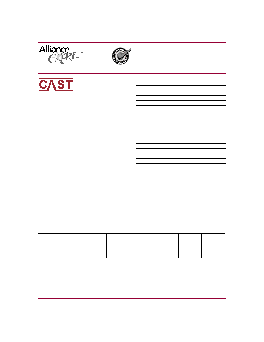
AllianceCORETM Facts
Core Specifics
See Table 1
Provided with Core
Documentation
Design document
Design File Formats
EDIF, .XNF Netlist
VHDL Source RTL
available extra
Constraints File
C8255A.ucf
Verification
VHDL testbench, test vectors
Instantiation Templates
VHDL, Verilog
Reference designs &
application notes
None
Additional Items
None
Simulation Tool Used
1076-compliant VHDL simulator, Verilog simulator
Support
Support provided by CAST, Inc.
C8255A Peripheral Interface
June 26, 2000
Product Specification
Table 1: Core Implementation Data
Supported
Family
Device
Tested
CLB
Slices
2
Clock
IOBs
IOBs
1
Performance
(MHz)
Xilinx
Tools
Special
Features
Virtex
V50-6
77
1
38
142
M2.1i
None
Virtex-E
V50E-8
77
1
38
227
M2.1i
None
Spartan-II
2S50-6
77
1
38
142
M2.1i
None
Notes:
1. Assuming all core I/Os are routed off-chip
2. Optimized for speed

C8255A Peripheral Interface
3-2
June 26, 2000
General Description
The C8255A core is a general purpose programmable I/O
device. It has 24 I/O pins programmable in 2 groups of 12
using 3 major modes. These modes allow the C8255A to
be programmed in various ways to combine these pins as
input, output or bi-directional ports.
Functional Description
The C8259A core is partitioned into modules as shown in
Figure 1 and described below.
Data Bus Buffer and Multiplexer
The Data Bus Buffer and Multiplexer block interfaces the
C8255A to the system Data Bus. Internally, this block mul-
tiplexes the peripheral busses PA, PB and PC.
Processor Read/Write Control
This block manages the internal and external transfers. It
sets up and controls all of the Control Groups (Data Ports).
Control Word Register
The Control Word is the register which contains the pro-
gramming of the C8255A.
Group A Port A
This block comprises the controls and buffer for Port A. Port
A is a single 8 bit port and is entirely in group A.
Group A Port C (upper)
This block comprises the controls and buffer for the upper
half of Port C. Port C has 4 bits in group A.
Group B Port B
This block comprises the controls and buffer for Port B. Port
B is a single 8 bit port and is entirely in group B.
Group A Port C (lower)
This block comprises the controls and buffer for the lower
half of Port C. Port C has 4 bits in group B.
Core Modifications
Additional ports can be added to this core by modifying the
source code. Since the Xilinx netlist version of the core is
not modifiable by the user, you would either need to pur-
chase the source code version of this core or have CAST
perform the modifications for you. Contact CAST directly for
additional information.
Figure 1: C8255A Peripheral Interface Block Diagram
Control Word
Register
Group A
Port C
Upper
Group B
Port C
Lower
Group B
Port B
Data Bus
Buffer
&
Multiplexer
Processor
Read/Write
Control
Group A
Port A
PA
PB
PC
CW
RDn
WRn
CSn
RESET
Processor Data Bus
Processor
Control
PA[7:0]
PC[3:0]
PB[7:0]
PC[7:4]
D[7:0]
A[1:0]
x8791
June 26, 2000
3-3
CAST, Inc.
Pinout
The pinout of the C8255A core has not been fixed to spe-
cific FPGA I/O, allowing flexibility with a user's application.
Signal names are shown in the block diagram in Figure 1
and descrive in Table 2.
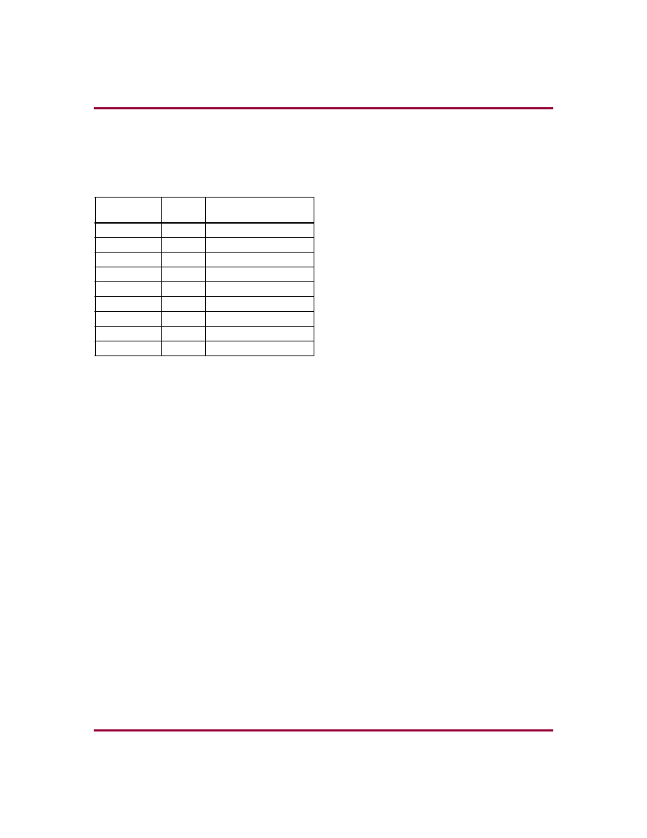
Table 2: Core Signal Pinout
Core Assumptions
Pull-up/Pull-down Bus Hold Devices
The Intel 8255A supports pull-up and pull-down bus hold
devices on Port A and pull-up bus hold devices on Ports B
and C. The C8255A model does not model this capability.
On devices with pull-up resistors attached to I/O, the pull-
up can be emulated. Otherwise external pull-up or pull-
down resistors can be used.
System Data Bus Writes - Hold Time
The Intel 8255A-2 Address and Chip Select Hold Time
After WRn Rising Edge is 20 ns minimum. On the C8255A
model, the Address Hold Time (determined by the imple-
mentation technology) is with respect to WRn or CSn rising
edge, which ever occurs first. That is to say, on system data
bus writes, data will be captured on the rising edge of WRn
or CSn, whichever occurs first.
Control Register Reads
The Intel 8255A does not support Control Register Reads
by way of the system data bus. The C8255A does. On
power-up reset, a read of this register yields 9B hexadeci-
mal.
Control Register Writes and Device
Reset
The Intel 8255A resets when the Control Register is pro-
grammed. The reset takes place with the WRn strobe's ris-
ing edge. The C8255A resets when the Control Register is
programmed, but the reset takes place on the WRn strobe's
low level. Note that a write to the Intel 8255A resets all
ports and that the device was not designed for on-the-fly
reprogramming.
Verification Methods
The C8255A core's functionality was verified by means of a
proprietary hardware modeler. The same stimulus was
applied to a hardware model which contained the original
Intel 8255A chip, and the results compared with the core's
simulation outputs.
Recommended Design
Experience
The user must be familiar with HDL design methodology as
well as instantiation of Xilinx netlists in a hierarchical design
environment.
Signal
Signal
Direction
Description
D[7:0]
In/Out
Data Bus
A[1:0]
Input
Address
RDn
Input
Read Control
WRn
Input
Write Control
CSn
Input
Chip Select
RESET
Input
Reset
PA[7:0]
In/Out
Port A
PC[7:0]
In/Out
Port B
PB[7:0]
In/Out
Port C

C8255A Peripheral Interface
3-4
June 26, 2000
Ordering Information
This product is available from CAST Inc. Please contact
CAST Inc. for pricing and more information.
Related Information
Intel Peripheral Components Data
Book
Intel order number: 296467
ISBN: 1-55512-127-6
Document number: 231308-002
Contact:
Intel Corporation
P.O. Box 7641
Mt. Prospect, IL 60056-7641
Phone:
800-548-4725
URL:
http://www.intel.com
Xilinx Programmable Logic
For information on Xilinx programmable logic or develop-
ment system software, contact your local Xilinx sales office,
or:
Xilinx, Inc.
2100 Logic Drive
San Jose, CA 95124
Phone:
+1 408-559-7778
Fax:
+1 408-559-7114
URL:
www.xilinx.com
For general Xilinx literature, contact:
Phone:
+1 800-231-3386 (inside the US)
+1 408-879-5017 (outside the US)
E-mail:
literature@xilinx.com
For AllianceCORETM specific information, contact:
Phone:
+1 408-879-5381
E-mail:
alliancecore@xilinx.com
URL:
www.xilinx.com/products/logicore/alliance/
tblpart.htm